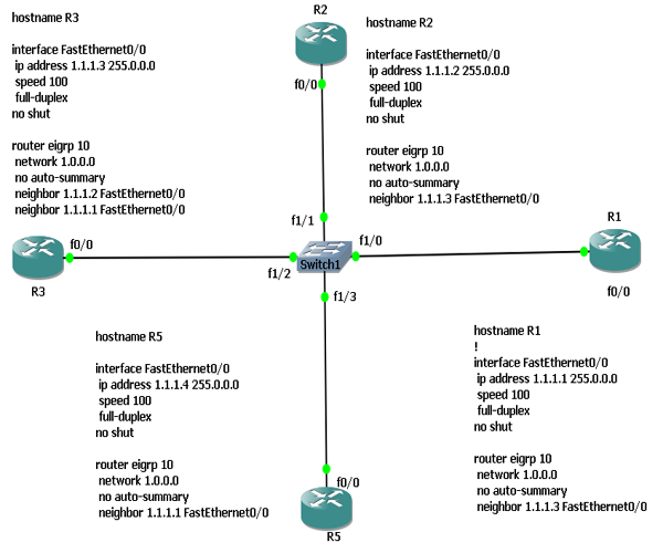
Based on the scenario, configuration and results. Explain why R5 do not make any neighbor relationship with any of Broadcast network.
Verification Results
R1#show ip eigrp neighbors
IP-EIGRP neighbors for process 10
H Address Interface Hold Uptime SRTT RTO Q Seq
(sec) (ms) Cnt Num
0 1.1.1.3 Fa0/0 11 00:01:22 295 1770 0 3
R2#show ip eigrp neighbors
IP-EIGRP neighbors for process 10
H Address Interface Hold Uptime SRTT RTO Q Seq
(sec) (ms) Cnt Num
0 1.1.1.3 Fa0/0 12 00:01:53 307 1842 0 5
R3#show ip eigrp neighbors
IP-EIGRP neighbors for process 10
H Address Interface Hold Uptime SRTT RTO Q Seq
(sec) (ms) Cnt Num
1 1.1.1.2 Fa0/0 13 00:02:09 107 642 0 3
0 1.1.1.1 Fa0/0 11 00:02:09 162 972 0 3
R5#show ip eigrp neighbors
IP-EIGRP neighbors for process 10
Explain why R5 do not have any neighbors
TASKS
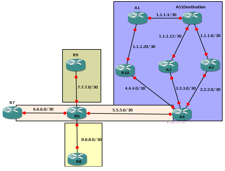
1. Configure IP Addresses on each link.
2. Configure Loopback address 100.100.100.1 on AS1Destination, 20.20.20.1 on A2, 70.70.70.1 on R7, 80.80.80.1 on R8 and 90.90.90.1 on R9.
3. Configure eigrp 50 on network 1.1.1.0/24, 2.2.2.0, 3.3.3.0, 4.4.4.0
4. Configure eigrp 100 for network 6.6.6.0 and 5.5.5.0.
5. Configure RIP on 7.7.7.0.
6. R6 should reach R8 loopbacks without any dynamic routing protocol.
7. Configure un-equal load balancing for AS1Destination on A2. Network 1.1.1.0 is a successor route. Put Feasable successor in the routing table too.
8. full network should reach each other with only exception of network 8.8.8.0; It should only be seen in R6 routing table only. Don't filter network 8.8.8.0 anywhere in network.
9. Eigrp shoul use only 30% bandwidth btw R7 and R6
10. R6 should Send summary route of network 1.1.1.0/24 to R7. Try to on output as summary network has different AD then non-summary network.
11. See Routing table and topology table on A3 and find equal-cost LB for net 20.20.20.1.
12. Debug all kind of packets. See Ack packet by shutting/no-shut an interface
13. Manipulate Eigrp Metric ( metric weight TOS value, K1, K2, K3, K4, K5). Change value other then 0 and 1 and see results
14. Change Administratice distance (distane Internal-AD External-AD)
15. Change bandwidth and Delay on interfaces
16. Change Eigrp utilization on interface via (ip band-perc eigrp 50 20)
17. Make sure that Eigrp uses 246 Kbps on R7 F0/0 but without using ip band-percentage command. [hint: Make actual bandwidth 1024 as by default Eigrp uses 50% bandwidth]
18. change Max hops of Eigrp (Metric Max-hop number)
19. Calculate EIGRP Metric by yourself
| hostname AS1Destination
interface Loopback0
ip address 100.100.100.1 255.255.255.255
!
interface FastEthernet0/0
ip address 1.1.1.5 255.255.255.252
no shut
!
interface FastEthernet0/1
ip address 1.1.1.1 255.255.255.252
no shut
!
interface FastEthernet1/0
ip address 1.1.1.13 255.255.255.252
no shut
!
router eigrp 50
network 1.0.0.0
network 100.0.0.0
no auto-summary
hostname A1
interface FastEthernet0/0
ip address 1.1.1.6 255.255.255.252
no shut
!
interface FastEthernet0/1
ip address 1.1.1.21 255.255.255.252
no shut
!
router eigrp 50
network 1.0.0.0
no auto-summary
hostname A2
interface Loopback0
ip address 20.20.20.1 255.255.255.255
!
interface FastEthernet0/0
ip address 1.1.1.2 255.255.255.252
no shut
!
interface FastEthernet0/1
ip address 2.2.2.1 255.255.255.252
no shut
!
router eigrp 50
variance 2
network 1.0.0.0
network 2.0.0.0
network 20.0.0.0
no auto-summary
hostname A3
interface FastEthernet0/0
ip address 1.1.1.14 255.255.255.252
speed 100
full-duplex
interface FastEthernet1/0
ip address 3.3.3.1 255.255.255.252
no shut
router eigrp 50
network 1.0.0.0
network 3.0.0.0
no auto-summary
hostname A4
interface FastEthernet0/0
ip address 3.3.3.2 255.255.255.252
speed 100
full-duplex
no shut
!
interface FastEthernet0/1
ip address 2.2.2.2 255.255.255.252
no shut
!
interface FastEthernet1/0
ip address 5.5.5.1 255.255.255.252
no shut
!
interface FastEthernet2/0
ip address 4.4.4.2 255.255.255.252
no shut
!
router eigrp 50
redistribute eigrp 100 metric 100 100 100 100 100
network 2.0.0.0
network 3.0.0.0
network 4.0.0.0
no auto-summary
!
router eigrp 100
redistribute eigrp 50 metric 100 100 100 100 100
network 5.0.0.0
no auto-summary
hostname R10
interface FastEthernet0/0
ip address 4.4.4.1 255.255.255.252
speed 100
full-duplex
no shut
interface FastEthernet0/1
ip address 1.1.1.22 255.255.255.252
no shut
router eigrp 50
network 1.0.0.0
network 4.0.0.0
no auto-summary
hostname R6
interface FastEthernet0/0
ip address 6.6.6.1 255.255.255.252
ip summary-address eigrp 100 1.1.1.0 255.255.255.0 5
no shut
!
interface FastEthernet0/1
ip address 5.5.5.2 255.255.255.252
speed 100
full-duplex
no shut
!
interface FastEthernet1/0
ip address 8.8.8.1 255.255.255.252
no shut
!
interface FastEthernet2/0
ip address 7.7.7.1 255.255.255.252
no shut
!
router eigrp 100
redistribute static metric 100 100 100 100 100
redistribute rip metric 100 100 100 100 100
network 5.0.0.0
network 6.0.0.0
no auto-summary
!
router rip
version 2
redistribute static metric 4
redistribute eigrp 100 metric 3
network 7.0.0.0
no auto-summary
!
ip route 80.80.80.1 255.255.255.255 8.8.8.2
hostname R7
interface Loopback0
ip address 70.70.70.1 255.255.255.255
!
interface FastEthernet0/0
ip address 6.6.6.2 255.255.255.252
no shut
!
router eigrp 100
network 6.0.0.0
network 70.0.0.0
no auto-summary
hostname R8
interface Loopback0
ip address 80.80.80.1 255.255.255.255
!
interface FastEthernet0/0
ip address 8.8.8.2 255.255.255.252
speed 100
full-duplex
no shut
!
ip route 0.0.0.0 0.0.0.0 8.8.8.1
hostname R9
interface Loopback0
ip address 90.90.90.1 255.255.255.255
!
interface FastEthernet0/0
ip address 7.7.7.2 255.255.255.252
speed 100
full-duplex
no shut
!
router rip
version 2
network 7.0.0.0
network 90.0.0.0
no auto-summary
| Explanation
|
IP SLA (Internet protocol service level agreement) is a feature of the Cisco Internetwork Operating System (Cisco IOS) that allows an IT professional to collect information about network performance in real time. Cisco IOS IP SLAs continuously collect data about such things as response times, latency, jitter and packet loss. This not only provides the network administrator with baseline information about network performance. IP SLAs are especially useful for wide area networks (WANs) that connect multiple geographies and needs to be monitored from one central location.

Requirement:- Configure IP addresses as per topology
- Configure EIGRP among ISP1 routers and between ISP1 and ISP2
- Configure Default and static routes as per need between customers and ISPs
- Configure SLA for icmp echo between customer 3 and customer 1.
- Configure SLA for path-echo between customer1 and customer2
verify results by using following commands - debug ip sla trace
- show ip sla statistics
- debug ip sla err
| ! Customer1 Configuration
interface Loopback0
ip address 150.1.1.1 255.255.255.255
interface Serial0/0
ip address 10.1.1.129 255.255.255.252
no shut
ip route 0.0.0.0 0.0.0.0 10.1.1.130
ip sla responder
ip sla 10
path-echo 10.1.1.194
verify-data
frequency 10
ip sla schedule 10 life 40 start-time now
! Cutomer2 Configuration
interface Loopback0
ip address 15.1.1.1 255.255.255.255
interface Serial0/0
ip address 10.1.1.194 255.255.255.252
no shut
ip route 0.0.0.0 0.0.0.0 10.1.1.193
ip sla responder
! Customer3 Configuration
interface Loopback0
ip address 90.1.1.1 255.255.255.255
interface Serial0/0
ip address 11.1.1.194 255.255.255.252
no shut
ip route 0.0.0.0 0.0.0.0 11.1.1.193
ip sla 1
icmp-echo 150.1.1.1
verify-data
frequency 5
ip sla schedule 1 life 60 start-time now
! ISPR1 Configuration
interface FastEthernet0/0
ip address 10.1.1.1 255.255.255.252
no shut
interface Serial0/0
ip address 10.1.1.130 255.255.255.252
no shut
router eigrp 10
redistribute static
network 10.0.0.0
no auto-summary
ip route 150.1.1.1 255.255.255.255 10.1.1.129
! ISP2R2 Configuration
interface FastEthernet0/0
ip address 10.1.1.2 255.255.255.252
no shut
interface Serial0/0
ip address 10.1.1.193 255.255.255.252
no shut
interface Serial0/1
ip address 11.1.1.1 255.255.255.252
no shut
router eigrp 10
redistribute static
network 10.0.0.0
network 11.0.0.0
no auto-summary
ip route 15.1.1.1 255.255.255.255 10.1.1.194
! ISP2R1 Configuration
interface Serial0/0
ip address 11.1.1.2 255.255.255.252
no shut
interface Serial0/1
ip address 11.1.1.193 255.255.255.252
no shut
router eigrp 10
redistribute static
network 11.0.0.0
no auto-summary
ip route 90.1.1.1 255.255.255.255 11.1.1.194
| Configuration Explanation
Providing ip address to loopback 0
Providing IP address to serial 0/0
Default Route
The Cisco IOS IP SLAs Responder is a component embedded in the destination Cisco routing device
that allows the system to anticipate and respond to Cisco IOS IP SLAs request packets. The Cisco IOS
IP SLAs Responder provides an enormous advantage with accurate measurements without the need for dedicated probes
Enabling IP SLA. Number is the identification of this SLA and it is locally important.
The IP SLAs ICMP Path Echo operation records statistics for each hop along the path that the IP SLAs operation takes to reach its destination.
(Optional) Causes an IP SLAs operation to check each reply packet for data corruption.
(Optional) Set the rate at which a specified IP SLAs operation repeats.
Configures the scheduling parameters for a single IP SLAs operation. use the ip sla schedule command in global configuration mode
|
Verification by Debugging
Customer3(config)#
*Mar 1 02:17:29.311: IP SLAs(1) Scheduler: Starting an operation
*Mar 1 02:17:29.311: IP SLAs(1) echo operation: Sending an echo operation -
destAddr=150.1.1.1, sAddr=11.1.1.194
*Mar 1 02:17:29.311: IP SLAs(1) echo operation: Sending ID: 7
*Mar 1 02:17:29.527: IP SLAs(1) echo operation: RTT=212
*Mar 1 02:17:29.527: IP SLAs(1) Scheduler: Updating result
*Mar 1 02:17:29.531: IP SLAs(1) Scheduler: life left 59784
*Mar 1 02:17:29.531: IP SLAs(1) Scheduler: is it random? 0
*Mar 1 02:17:29.531: IP SLAs(1) Scheduler: start wakeup timer, delay = 4780
*Mar 1 02:17:34.311: IP SLAs(1) Scheduler: saaSchedulerEventWakeup
*Mar 1 02:17:34.311: IP SLAs(1) Scheduler: Starting an operation
*Mar 1 02:17:34.311: IP SLAs(1) echo operation: Sending an echo operation -
destAddr=150.1.1.1, sAddr=11.1.1.194
*Mar 1 02:17:34.315: IP SLAs(1) echo operation: Sending ID: 7
*Mar 1 02:17:34.427: IP SLAs(1) echo operation: RTT=112
*Mar 1 02:17:34.427: IP SLAs(1) Scheduler: Updating result
*Mar 1 02:17:34.427: IP SLAs(1) Scheduler: life left 54884
*Mar 1 02:17:34.431: IP SLAs(1) Scheduler: is it random? 0
*Mar 1 02:17:34.431: IP SLAs(1) Scheduler: start wakeup timer, delay = 4880
Customer1(config)#
*Mar 1 02:33:24.391: IP SLAs(10) Scheduler: Starting an operation
*Mar 1 02:33:24.395: IP SLAs(10) pathEcho operation: Sending a pathEcho operation
*Mar 1 02:33:24.399: IP SLAs(10) pathEcho operation: Sending Packet to 10.1.1.194 with ttl = 1
*Mar 1 02:33:24.407: IP SLAs(10) pathEcho operation: Return Value of ! for target 10.1.1.130
*Mar 1 02:33:24.407: IP SLAs(10) pathEcho operation: Adding hop - 10.1.1.130
*Mar 1 02:33:24.407: IP SLAs(10) pathEcho operation: Sending Packet to 10.1.1.194 with ttl = 2
*Mar 1 02:33:24.619: IP SLAs(10) pathEcho operation: Return Value of ! for target 10.1.1.2
*Mar 1 02:33:24.623: IP SLAs(10) pathEcho operation: Adding hop - 10.1.1.2
*Mar 1 02:33:24.623: IP SLAs(10) pathEcho operation: Sending Packet to 10.1.1.194 with ttl = 3
*Mar 1 02:33:24.823: IP SLAs(10) pathEcho operation: Return Value of U for target 10.1.1.194
*Mar 1 02:33:24.823: IP SLAs(10) pathEcho operation: Adding hop - 10.1.1.194
*Mar 1 02:33:24.951: IP SLAs(10) pathEcho operation: Hop 10.1.1.130 Response Time 124
*Mar 1 02:33:25.103: IP SLAs(10) pathEcho operation: Hop 10.1.1.2 Response Time 152
*Mar 1 02:33:25.255: IP SLAs(10) pathEcho operation: Hop 10.1.1.194 Response Time 149
*Mar 1 02:33:25.255: IP SLAs(10) Scheduler: Updating result
*Mar 1 02:33:25.263: IP SLAs(10) Scheduler: life left 39128
*Mar 1 02:33:25.263: IP SLAs(10) Scheduler: is it random? 0
*Mar 1 02:33:25.263: IP SLAs(10) Scheduler: start wakeup timer, delay = 9128
Customer1(config)#
In this scenerio; we are trying to communicate two customers via MPLS SP cloud.
A CE router ( customer edge router ) is a router located on the customer premises that provides an Ethernet interface between the customer's LAN and the provider's core network. CE routers, P (provider) routers and PE (provider edge) routers are components in an MPLS (multiprotocol label switching) architecture. Provider routers are located in the core of the provider or carrier's network. Provider edge routers sit at the edge of the network. CE routers connect to PE routers and PE routers connect to other PE routers over P routers.

Requirement:
- Configure IP address as per toplogy
- Configure 2.2.2.2 as PE2 router ID, 3.3.3.3 P2 router ID, 4.4.4.4 P1 router ID and 1.1.1.1 as PE1 router ID.
- Configure EIGRP as a routing protocol
- Configure MPLS with-in cloud.
- Verify communication via MPLS
Verificaton Command- show mpls ip binding
- show ip cef
- show mpls interfaces
- show mpls ldp discovery
- show mpls ldp nei
- show mpls forwarding-table
| ! CE1 Configuration
ip cef
interface FastEthernet1/0
ip address 200.1.2.1 255.255.255.0
no shut
router eigrp 10
network 200.1.2.0
no auto-summary
! CE2 Configuration
ip cef
interface Loopback0
ip address 10.1.1.1 255.255.255.0
interface FastEthernet1/0
ip address 200.1.1.1 255.255.255.0
no shut
router eigrp 10
network 10.0.0.0
network 200.1.1.0
no auto-summary
! PE1 Configuration
ip cef
mpls label protocol ldp
interface Loopback0
ip address 1.1.1.1 255.255.255.255
interface FastEthernet1/0
ip address 200.1.2.2 255.255.255.0
no shut
interface Serial2/0
ip address 200.1.7.1 255.255.255.0
mpls label protocol ldp
mpls ip
no shut
interface Serial2/1
ip address 200.1.6.1 255.255.255.0
mpls label protocol ldp
mpls ip
no shut
router eigrp 10
network 1.0.0.0
network 200.1.2.0
network 200.1.6.0
network 200.1.7.0
no auto-summary
! PE2 Configuration
ip cef
mpls label protocol ldp
interface Loopback0
ip address 2.2.2.2 255.255.255.255
interface FastEthernet1/0
ip address 200.1.1.2 255.255.255.0
no shut
interface Serial2/0
ip address 200.1.4.1 255.255.255.0
mpls label protocol ldp
mpls ip
no shut
!
interface Serial2/1
ip address 200.1.3.1 255.255.255.0
mpls label protocol ldp
mpls ip
no shut
router eigrp 10
network 2.0.0.0
network 200.1.1.0
network 200.1.3.0
network 200.1.4.0
no auto-summary
! P1 Configuration
ip cef
mpls label protocol ldp
interface Loopback0
ip address 4.4.4.4 255.255.255.255
interface Serial1/0
ip address 200.1.7.2 255.255.255.0
mpls label protocol ldp
mpls ip
no shut
!
interface Serial1/1
ip address 200.1.4.2 255.255.255.0
mpls label protocol ldp
mpls ip
no shut
!
interface Serial1/2
ip address 200.1.5.2 255.255.255.0
mpls label protocol ldp
mpls ip
no shut
router eigrp 10
network 4.0.0.0
network 200.1.4.0
network 200.1.5.0
network 200.1.7.0
no auto-summary
!P2 Configuration
ip cef
mpls label protocol ldp
interface Loopback0
ip address 3.3.3.3 255.255.255.255
!
interface Serial1/0
ip address 200.1.6.2 255.255.255.0
mpls label protocol ldp
mpls ip
no shut
!
interface Serial1/1
ip address 200.1.3.2 255.255.255.0
mpls label protocol ldp
mpls ip
no shut
!
interface Serial1/2
ip address 200.1.5.1 255.255.255.0
mpls label protocol ldp
mpls ip
no shut
router eigrp 10
network 3.0.0.0
network 200.1.3.0
network 200.1.5.0
network 200.1.6.0
no auto-summary
| Configuration Explanation
Cisco's Express Forwarding (CEF) is an Layer 3 fastest switching technology by which Cisco router forwards packets from ingress to egress interfaces.
Note: This is a essential command
For explanation; See above
Enabling IP address to loopback interface
Enabling EIGRP autonomous no 10
See above for command explanation
Enable LDP protocol globally. MPLS Label Distribution Protocol (LDP) enables peer label switch routers (LSRs) in an MPLS network to exchange label binding information for supporting hop-by-hop forwarding in an MPLS network
Globally enabling MPLS forwarding does not enable it on the router interfaces. You must enable MPLS forwarding on the interfaces as well as for the router. |
CE1#traceroute 10.1.1.1 ====> Look at the output; MPLs is working
Type escape sequence to abort.
Tracing the route to 10.1.1.1
1 200.1.2.2 80 msec 44 msec 32 msec
2 200.1.7.2 [MPLS: Label 23 Exp 0] 80 msec 64 msec 60 msec
3 200.1.4.1 [MPLS: Label 23 Exp 0] 172 msec 60 msec 76 msec
4 200.1.1.1 92 msec * 176 msec
check all verification commands by yourself.
 RSS Feed