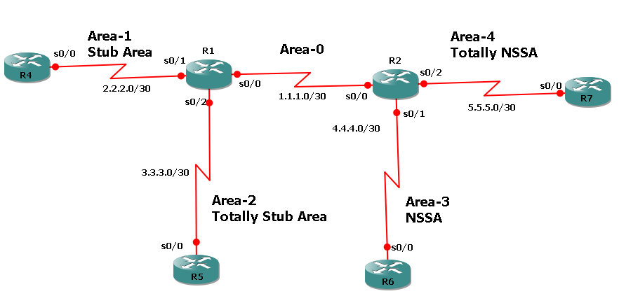
| ! R1 Configuration
hostname R1
interface Loopback0
ip address 10.1.1.1 255.255.255.255
interface Serial0/0
ip address 1.1.1.1 255.255.255.252
no shut
interface Serial0/1
ip address 2.2.2.1 255.255.255.252
no shut
interface Serial0/2
ip address 3.3.3.1 255.255.255.252
no shut
router ospf 10
network 1.1.1.0 0.0.0.3 area 0
network 2.2.2.0 0.0.0.3 area 1
network 3.3.3.0 0.0.0.3 area 2
area 1 stub
area 2 stub no-summary
redistribute connected subnets
! R4 Configuration
hostname R4
interface Loopback0
ip address 40.1.1.1 255.255.255.255
interface Serial0/0
ip address 2.2.2.2 255.255.255.252
no shut
router ospf 10
network 2.2.2.0 0.0.0.3 area 1
area 1 stub
redistribute connected subnets
! R6 Configuration
hostname R6
interface Loopback0
ip address 60.1.1.1 255.255.255.255
!
interface Serial0/0
ip address 4.4.4.2 255.255.255.252
no shut
!
router ospf 10
network 4.4.4.0 0.0.0.3 area 3
area 3 nssa
redistribute connected subnets
| ! R2 Configuration
hostname R2
interface Loopback0
ip address 20.1.1.1 255.255.255.255
interface Serial0/0
ip address 1.1.1.2 255.255.255.252
no shut
interface Serial0/1
ip address 4.4.4.1 255.255.255.252
no shut
interface Serial0/2
ip address 5.5.5.1 255.255.255.252
no shut
router ospf 10
network 1.1.1.0 0.0.0.3 area 0
network 4.4.4.0 0.0.0.3 area 3
network 5.5.5.0 0.0.0.3 area 4
area 3 nssa default-information-originate
area 4 nssa no-summary
redistribute connected subnets
! R5 Configuration
hostname R5
interface Loopback0
ip address 50.1.1.1 255.255.255.255
interface Serial0/0
ip address 3.3.3.2 255.255.255.252
no shut
router ospf 10
network 3.3.3.0 0.0.0.3 area 2
area 2 stub no-summary
redistribute connected subnets
! R7 Configuration
hostname R7
interface Loopback0
ip address 70.1.1.1 255.255.255.255
!
interface Serial0/0
ip address 5.5.5.2 255.255.255.252
no shut
router ospf 10
network 5.5.5.0 0.0.0.3 area 4
area 4 nssa no-summary
redistribute connected subnets
|
Verification commands:
Show ip route
Show ip ospf border-router
Show ip ospf interface s0/0
show ip ospf neighbor
show ip ospf database
Debug ip ospf adj
Debug ip ospf packet

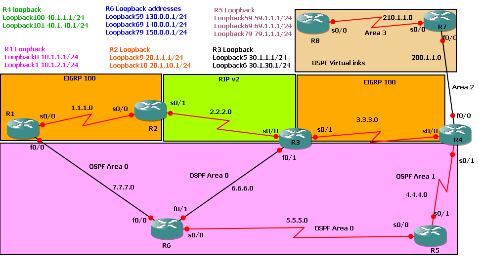
TASKS:
1. Configure IP Addresses as per diagram
2. Configure 5 subnet of 20.0.0.0/8 as loopback addresses in R3
3. Look into routing table inter-area routes
4. Configure Area Range command on R2 and see change in Routing table of R1. Area range command summarizes range and only work on Border Routers.
5. See Results by using Show ip route; show ip protocols
6. Dubug ip ospf adj and Debug ip ospf events
| ! R1 Configuration
hostname R1 !
interface Serial0/0
ip address 1.1.1.1 255.255.255.252
no shut
!
interface Serial0/1
ip address 2.2.2.1 255.255.255.252
no shut
!
router ospf 1
network 1.1.1.0 0.0.0.3 area 0
network 2.2.2.0 0.0.0.3 area 10
! R2 Configuration
hostname R2
interface Serial0/0
ip address 1.1.1.2 255.255.255.252
no shut
!
interface Serial0/1
ip address 3.3.3.1 255.255.255.252
no shut
!
router ospf 1
area 20 range 20.1.1.0 255.255.255.0
network 1.1.1.0 0.0.0.3 area 0
network 3.3.3.0 0.0.0.3 area 20
| ! R3 Configuration
hostname R3
interface Loopback0
ip address 20.1.1.1 255.255.255.255
interface Loopback1
ip address 20.1.1.2 255.255.255.255
interface Loopback2
ip address 20.1.1.3 255.255.255.255
interface Loopback3
ip address 20.1.1.4 255.255.255.255
interface Loopback4
ip address 20.1.1.5 255.255.255.255
!
interface Serial0/0
ip address 3.3.3.2 255.255.255.252
no shut
!
router ospf 1
network 3.3.3.0 0.0.0.3 area 20
network 20.1.1.1 0.0.0.0 area 20
network 20.1.1.2 0.0.0.0 area 20
network 20.1.1.3 0.0.0.0 area 20
network 20.1.1.4 0.0.0.0 area 20
network 20.1.1.5 0.0.0.0 area 20
! R4 Configuration
hostname R4
interface Serial0/0
ip address 2.2.2.2 255.255.255.252
no shut
!
router ospf 1
network 2.2.2.0 0.0.0.3 area 10
|

Requirement:
- Configure ip addresses as per topology
- Configure one loopback address on each router i.e. 10.10.10.10 on R1 ; 20.20.20.20 on R2 ; 30.30.30.30 on R3 ; 40.40.40.40 on R4 and 50.50.50.50 on R5
- Configure ospf on specified networks
- Configure ibgp and ebgp as per topology
- Configure MPLS on core network
- Verify connectivity annd communication via mpls
Verification commands: - traceroute ip 50.50.50.50 source 40.40.40.40
- traceroute mpls ipv4 50.50.50.50/32 (very imp)
- ping mpls ipv4 30.30.30.30/32
- sh ip route :: Show ip bgp :: clear ip bgp *
- show mpls ldp neigehbor
- show mpls forwarding
- show mpls ldp binding
| ! R1 configuration
hostname R1
ip cef
mpls label protocol ldp
interface Loopback0
ip address 10.10.10.10 255.255.255.0
interface Serial0/0
ip address 1.1.1.1 255.255.255.0
mpls ip
no shut
interface Serial0/1
ip address 9.9.9.1 255.255.255.252
no shut
router ospf 10
redistribute bgp 10 subnets
network 1.1.1.0 0.0.0.255 area 0
network 10.10.10.10 0.0.0.0 area 0
router bgp 10
neighbor 9.9.9.2 remote-as 100
neighbor 9.9.9.2 distribute-list 1 out
neighbor 30.30.30.30 remote-as 10
neighbor 30.30.30.30 update-source Loopback0
neighbor 30.30.30.30 next-hop-self
no auto-summary
access-list 1 deny 50.50.50.50
access-list 1 permit any
! R2 Configuration
hostname R2
ip cef
mpls label protocol ldp
interface Loopback0
ip address 20.20.20.20 255.255.255.255
interface Serial0/0
ip address 1.1.1.2 255.255.255.0
mpls ip
no shut
interface Serial0/1
ip address 1.1.10.1 255.255.255.0
mpls ip
no shut
router ospf 10
network 1.1.1.0 0.0.0.255 area 0
network 1.1.10.0 0.0.0.255 area 0
network 20.20.20.20 0.0.0.0 area 0
| ! R3 Configuration
hostname R3
ip cef
mpls label protocol ldp
interface Loopback0
ip address 30.30.30.30 255.255.255.255
interface Serial0/0
ip address 1.1.10.11 255.255.255.0
mpls ip
no shut
interface Serial0/1
ip address 6.6.6.1 255.255.255.252
no shut
router ospf 10
redistribute bgp 10 subnets
network 1.1.10.0 0.0.0.255 area 0
network 30.30.30.30 0.0.0.0 area 0
router bgp 10
neighbor 6.6.6.2 remote-as 200
neighbor 6.6.6.2 distribute-list 1 out
neighbor 10.10.10.10 remote-as 10
neighbor 10.10.10.10 update-source Loopback0
neighbor 10.10.10.10 next-hop-self
no auto-summary
access-list 1 deny 40.40.40.40
access-list 1 permit any
! R4 Configuration
hostname R4
interface Loopback0
ip address 40.40.40.40 255.255.255.255
interface Serial0/0
ip address 9.9.9.2 255.255.255.252
no shut
router bgp 100
network 40.40.40.40 mask 255.255.255.255
neighbor 9.9.9.1 remote-as 10
no auto-summary
ip route 0.0.0.0 0.0.0.0 9.9.9.1
! R5 Configuration
hostname R5
interface Loopback0
ip address 50.50.50.50 255.255.255.255
interface Serial0/0
ip address 6.6.6.2 255.255.255.252
no shut
router bgp 200
network 50.50.50.50 mask 255.255.255.255
neighbor 6.6.6.1 remote-as 10
no auto-summary
ip route 0.0.0.0 0.0.0.0 6.6.6.1
|
Verification:
R4#traceroute ip 50.50.50.50 source 40.40.40.40
Type escape sequence to abort.
Tracing the route to 50.50.50.50
1 9.9.9.1 56 msec 4 msec 8 msec
2 1.1.1.2 [MPLS: Label 16 Exp 0] 72 msec 16 msec 0 msec
3 1.1.10.11 60 msec 44 msec 20 msec
4 6.6.6.2 64 msec * 132 msec
R1#show mpls forwarding
Local Outgoing Prefix Bytes tag Outgoing Next Hop
tag tag or VC or Tunnel Id switched interface
16 Pop tag 1.1.10.0/24 0 Se0/0 point2point
17 16 50.50.50.50/32 0 Se0/0 point2point
18 Pop tag 20.20.20.20/32 0 Se0/0 point2point
19 19 30.30.30.30/32 0 Se0/0 point2point
R1#
R2#show mpls ldp neighbor
Peer LDP Ident: 10.10.10.10:0; Local LDP Ident 20.20.20.20:0
TCP connection: 10.10.10.10.646 - 20.20.20.20.53911
State: Oper; Msgs sent/rcvd: 151/151; Downstream
Up time: 02:00:22
LDP discovery sources:
Serial0/0, Src IP addr: 1.1.1.1
Addresses bound to peer LDP Ident:
1.1.1.1 9.9.9.1 10.10.10.10
Peer LDP Ident: 30.30.30.30:0; Local LDP Ident 20.20.20.20:0
TCP connection: 30.30.30.30.37364 - 20.20.20.20.646
State: Oper; Msgs sent/rcvd: 145/147; Downstream
Up time: 01:59:44
LDP discovery sources:
Serial0/1, Src IP addr: 1.1.10.11
Addresses bound to peer LDP Ident:
1.1.10.11 6.6.6.1 30.30.30.30
In this scenario; We are trying to built a topology in which four customers wanna communicate each other via frame relay cloud. Normally labs are done with one FR device but what about when we are working as a WAN service provider having so many devices in their cloud. Let's see how customers of TelcoRemote2 will communicate to customer of TelcoKHI.
We will built a tunnel for this purpose and use OSPF as a routing protocol between Cloud. Let's see detail

Requirement:- Configure all IP addresses as per topology
- Assign DLCI's to all customers
- Assign Route to all customers so that they will communicate each other seamlessly
- Configure OSPF area 0 for network 10.1.1.0 and 20.1.1.0
- Configure tunnel so that Remote customer can communicate to Site1, 2 and 3 customers.
- Verify connectivity with
ping command
show frame-relay map
show frame-relay route
show frame-relay pvc
debug frame-relay packet
debug frame-relay pvc
debug frame-relay event
| !CustomerSite1 Configuration
interface Serial0/0
ip address 1.1.1.1 255.255.255.0
encapsulation frame-relay
frame-relay interface-dlci 101
frame-relay interface-dlci 102
frame-relay interface-dlci 103
frame-relay interface-dlci 104
no shut
!CustomerSite2 Configuration
interface Serial0/0
ip address 2.2.2.2 255.255.255.0
encapsulation frame-relay
frame-relay interface-dlci 201
frame-relay interface-dlci 202
frame-relay interface-dlci 203
frame-relay interface-dlci 204
no shut
! CustomerSite3 Configuration
interface Serial0/0
ip address 3.3.3.3 255.255.255.0
encapsulation frame-relay
frame-relay interface-dlci 301
frame-relay interface-dlci 302
frame-relay interface-dlci 303
frame-relay interface-dlci 304
no shut
! Telco remote2 Configuration
frame-relay switching
interface Serial0/0
no ip address
encapsulation frame-relay
clock rate 64000
frame-relay intf-type dce
frame-relay route 102 interface Serial0/1 201
frame-relay route 103 interface Serial0/2 301
frame-relay route 104 interface Tunnel0 401
no shut
interface Serial0/1
no ip address
encapsulation frame-relay
clock rate 64000
frame-relay intf-type dce
frame-relay route 201 interface Serial0/0 102
frame-relay route 203 interface Serial0/2 302
frame-relay route 204 interface Tunnel0 402
no shut
interface Serial0/2
no ip address
encapsulation frame-relay
clock rate 64000
frame-relay intf-type dce
frame-relay route 301 interface Serial0/0 103
frame-relay route 302 interface Serial0/1 203
frame-relay route 304 interface Tunnel0 403
no shut
interface fastethernet 0/0
ip address 10.1.1.1 255.255.255.252
no shut
interface tunnel 0
no ip address
tunnel source 10.1.1.1
tunnel destination 20.1.1.1
Router OSPF 10
network 10.1.1.0 0.0.0.3 area 0
! R7 Configuration
interface fastethernet 0/0
ip address 10.1.1.2 255.255.255.252
no shut
interface fastethernet 0/1
ip address 20.1.1.2 255.255.255.252
no shut
Router OSPF 10
network 10.1.1.0 0.0.0.3 area 0
network 20.1.1.0 0.0.0.3 area 0
! Telco KHI Configuration
frame-relay switching
interface Serial0/2
no ip address
encapsulation frame-relay
clock rate 64000
frame-relay intf-type dce
! Note both dlcis are same in all routes
frame-relay route 401 interface Tunnel0 401
frame-relay route 402 interface Tunnel0 402
frame-relay route 403 interface Tunnel0 403
no shut
interface fastethernet 0/0
ip address 20.1.1.1 255.255.255.252
no shut
interface tunnel 0
no ip address
tunnel source 20.1.1.1
tunnel destination 10.1.1.1
Router OSPF 10
network 20.1.1.0 0.0.0.3 area 0
! RemoteCustomer Configuration
interface Serial0/0
ip address 15.15.15.1 255.255.255.0
encapsulation frame-relay
frame-relay interface-dlci 401
frame-relay interface-dlci 402
frame-relay interface-dlci 403
frame-relay interface-dlci 404
no shut
| Configuration Explanation
Configuring IP on customer interface
encapsulation frame-relay command sets the frame encapsulation type. There are two types of Frame Relay encapsulations: Cisco and IETF. Cisco is the default.
We are putting many DLCI's to one physical serial interface.
See Site1 Explanation
See Site1 Explanation
This is a key command on FR switches on service provider side. Forget this command; Forget FR switching. Anyhow; If you try to configure interface type dce without this; you will get error.
As this interface word as a FR enabled interface; it donot require IP address.
Setting encapsulation type
Setting clock rate
FR switch interface must be DCE
This command is telling that DLCI 102, 103, 104 should route toward said interface
Creating tunnel from source 10.1.1.1 (interface F0/0) to destination 20.1.1.1 (int F0/0)
This is a key for tunneling Frame relay. Both DLCI's should be same in each command else you will find status Inactive
|

OSPF stands for Open Shortest Path First. It is an internal routing protocol of the autonomous system based on link state. Routers running the SPF (Shortest Path First) algorithm Dijkshtra to be precise build a shortest path tree that takes itself as the root, and the tree gives out the route to nodes in the autonomous system.
Within OSPF there can be Point-to-Point networks or Multi-Access networks. The Multi-Access networks could be one of the following:
- Broadcast Network: A single message can be sent to all routers
- Non-Broadcast Multi-Access (NBMA) Network: Has no broadcast ability, ISDN, ATM, Frame Relay and X.25 are examples of NBMA networks.
- Point to Multipoint Network: Used in group mode Frame Relay networks.
Requirement:- Enable and configure interfaces as per topology diagram
- Configure one loop back addresses on each router
- Configure OSPF area 0 on both routers so that they both can get all routes
| ! R2 Configuration
interface Loopback0
ip address 10.1.1.1 255.255.255.0
interface Serial0/0
ip address 1.1.1.1 255.255.255.252
no shut
router ospf 10
network 1.1.1.0 0.0.0.3 area 0
network 10.1.1.0 0.0.0.255 area 0
| ! R3 Configuration
interface Loopback0
ip address 100.1.1.1 255.255.255.255
!
interface Serial0/0
ip address 1.1.1.2 255.255.255.252
no shut
!
router ospf 10
network 1.1.1.0 0.0.0.3 area 0
network 100.1.1.1 0.0.0.0 area 0
|
Verification commands
R2#show ip ospf neighbor ==========> To find out information about OSPF neighbors
Neighbor ID Pri State Dead Time Address Interface
100.1.1.1 0 FULL/ - 00:00:36 1.1.1.2 Serial0/0
Look at the neighbor ID; its the loopback address
R3#show ip ospf neighbor
Neighbor ID Pri State Dead Time Address Interface
10.1.1.1 0 FULL/ - 00:00:30 1.1.1.1 Serial0/0
Look at the neighbor ID; its the loopback address
R2#show ip route ospf ==========> Only OSPF routes
100.0.0.0/32 is subnetted, 1 subnets
O 100.1.1.1 [110/65] via 1.1.1.2, 00:34:12, Serial0/0
R3#show ip route ospf
10.0.0.0/32 is subnetted, 1 subnets
O 10.1.1.1 [110/65] via 1.1.1.1, 00:34:12, Serial0/0
R2#show ip route ==========> ALL routes coming to routing table
Gateway of last resort is not set
1.0.0.0/30 is subnetted, 1 subnets
C 1.1.1.0 is directly connected, Serial0/0
100.0.0.0/32 is subnetted, 1 subnets
O 100.1.1.1 [110/65] via 1.1.1.2, 00:36:01, Serial0/0
10.0.0.0/24 is subnetted, 1 subnets
C 10.1.1.0 is directly connected, Loopback0
R3#show ip route
Gateway of last resort is not set
1.0.0.0/30 is subnetted, 1 subnets
C 1.1.1.0 is directly connected, Serial0/0
100.0.0.0/32 is subnetted, 1 subnets
C 100.1.1.1 is directly connected, Loopback0
10.0.0.0/32 is subnetted, 1 subnets
O 10.1.1.1 [110/65] via 1.1.1.1, 00:36:01, Serial0/0
R2#show ip protocols
Routing Protocol is "ospf 10" ==========> This is OSPF process ID
Outgoing update filter list for all interfaces is not set
Incoming update filter list for all interfaces is not set
Router ID 10.1.1.1 ==========> Router ID
Number of areas in this router is 1. 1 normal 0 stub 0 nssa
Maximum path: 4
Routing for Networks:
1.1.1.0 0.0.0.3 area 0
10.1.1.0 0.0.0.7 area 0
10.1.1.0 0.0.0.255 area 0
Reference bandwidth unit is 100 mbps
Routing Information Sources:
Gateway Distance Last Update
100.1.1.1 110 00:38:01 ==========> Administrative distance
Distance: (default is 110) ==========> OSPF default Administrative distance
R3#show ip protocols
Routing Protocol is "ospf 10"
Outgoing update filter list for all interfaces is not set
Incoming update filter list for all interfaces is not set
Router ID 100.1.1.1
Number of areas in this router is 1. 1 normal 0 stub 0 nssa
Maximum path: 4
Routing for Networks:
1.1.1.0 0.0.0.3 area 0
100.1.1.1 0.0.0.0 area 0
Reference bandwidth unit is 100 mbps
Routing Information Sources:
Gateway Distance Last Update
10.1.1.1 110 00:38:01
Distance: (default is 110)
 RSS Feed