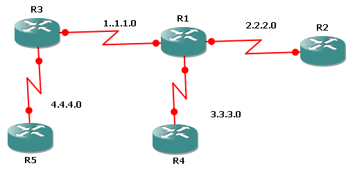
| ! R1 Configuration
hostname R1
interface Loopback0
ip address 10.1.1.1 255.255.255.255
interface Serial0/0
ip address 1.1.1.1 255.255.255.252
no shut
interface Serial0/1
ip address 2.2.2.1 255.255.255.252
no shut
interface Serial0/2
ip address 3.3.3.1 255.255.255.252
no shut
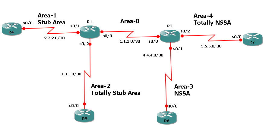
router ospf 10
network 1.1.1.0 0.0.0.3 area 0
network 2.2.2.0 0.0.0.3 area 1
network 3.3.3.0 0.0.0.3 area 2
area 1 stub
area 2 stub no-summary
redistribute connected subnets
! R4 Configuration
hostname R4
interface Loopback0
ip address 40.1.1.1 255.255.255.255
interface Serial0/0
ip address 2.2.2.2 255.255.255.252
no shut
router ospf 10
network 2.2.2.0 0.0.0.3 area 1
area 1 stub
redistribute connected subnets
! R6 Configuration
hostname R6
interface Loopback0
ip address 60.1.1.1 255.255.255.255
!
interface Serial0/0
ip address 4.4.4.2 255.255.255.252
no shut
!
router ospf 10
network 4.4.4.0 0.0.0.3 area 3
area 3 nssa
redistribute connected subnets
| ! R2 Configuration
hostname R2
interface Loopback0
ip address 20.1.1.1 255.255.255.255
interface Serial0/0
ip address 1.1.1.2 255.255.255.252
no shut
interface Serial0/1
ip address 4.4.4.1 255.255.255.252
no shut
interface Serial0/2
ip address 5.5.5.1 255.255.255.252
no shut
router ospf 10
network 1.1.1.0 0.0.0.3 area 0
network 4.4.4.0 0.0.0.3 area 3
network 5.5.5.0 0.0.0.3 area 4
area 3 nssa default-information-originate
area 4 nssa no-summary
redistribute connected subnets
! R5 Configuration
hostname R5
interface Loopback0
ip address 50.1.1.1 255.255.255.255
interface Serial0/0
ip address 3.3.3.2 255.255.255.252
no shut
router ospf 10
network 3.3.3.0 0.0.0.3 area 2
area 2 stub no-summary
redistribute connected subnets
! R7 Configuration
hostname R7
interface Loopback0
ip address 70.1.1.1 255.255.255.255
!
interface Serial0/0
ip address 5.5.5.2 255.255.255.252
no shut
router ospf 10
network 5.5.5.0 0.0.0.3 area 4
area 4 nssa no-summary
redistribute connected subnets
|
Verification commands:
Show ip route
Show ip ospf border-router
Show ip ospf interface s0/0
show ip ospf neighbor
show ip ospf database
Debug ip ospf adj
Debug ip ospf packet
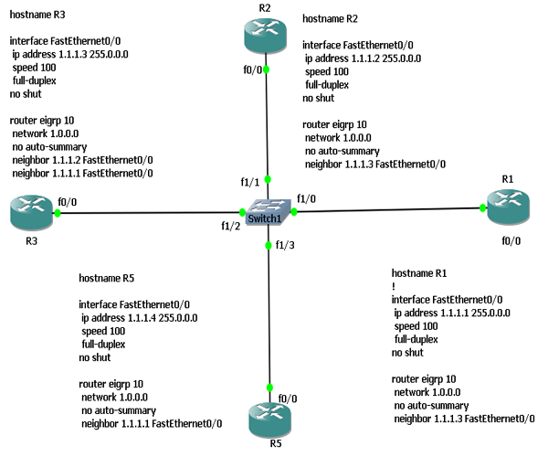
Based on the scenario, configuration and results. Explain why R5 do not make any neighbor relationship with any of Broadcast network.
Verification Results
R1#show ip eigrp neighbors
IP-EIGRP neighbors for process 10
H Address Interface Hold Uptime SRTT RTO Q Seq
(sec) (ms) Cnt Num
0 1.1.1.3 Fa0/0 11 00:01:22 295 1770 0 3
R2#show ip eigrp neighbors
IP-EIGRP neighbors for process 10
H Address Interface Hold Uptime SRTT RTO Q Seq
(sec) (ms) Cnt Num
0 1.1.1.3 Fa0/0 12 00:01:53 307 1842 0 5
R3#show ip eigrp neighbors
IP-EIGRP neighbors for process 10
H Address Interface Hold Uptime SRTT RTO Q Seq
(sec) (ms) Cnt Num
1 1.1.1.2 Fa0/0 13 00:02:09 107 642 0 3
0 1.1.1.1 Fa0/0 11 00:02:09 162 972 0 3
R5#show ip eigrp neighbors
IP-EIGRP neighbors for process 10
Explain why R5 do not have any neighbors
TASKS
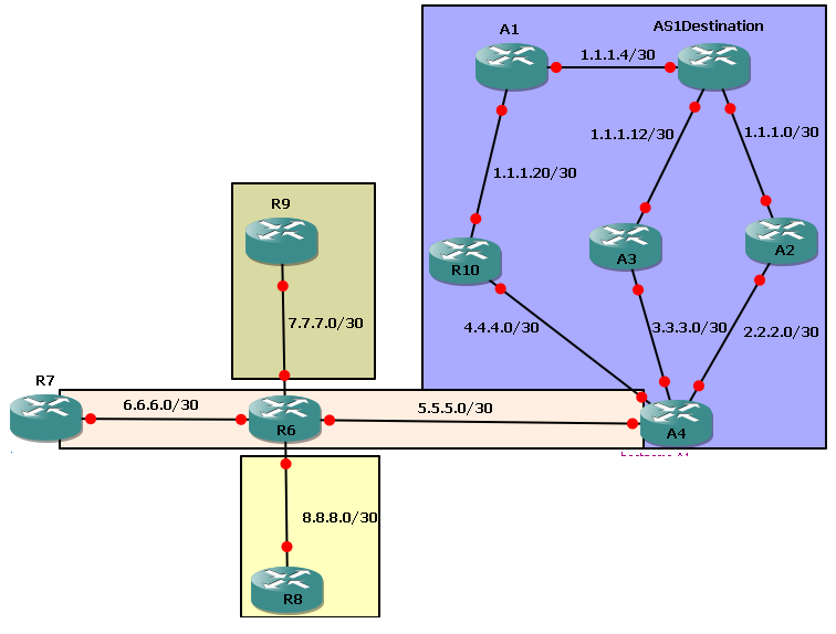
1. Configure IP Addresses on each link.
2. Configure Loopback address 100.100.100.1 on AS1Destination, 20.20.20.1 on A2, 70.70.70.1 on R7, 80.80.80.1 on R8 and 90.90.90.1 on R9.
3. Configure eigrp 50 on network 1.1.1.0/24, 2.2.2.0, 3.3.3.0, 4.4.4.0
4. Configure eigrp 100 for network 6.6.6.0 and 5.5.5.0.
5. Configure RIP on 7.7.7.0.
6. R6 should reach R8 loopbacks without any dynamic routing protocol.
7. Configure un-equal load balancing for AS1Destination on A2. Network 1.1.1.0 is a successor route. Put Feasable successor in the routing table too.
8. full network should reach each other with only exception of network 8.8.8.0; It should only be seen in R6 routing table only. Don't filter network 8.8.8.0 anywhere in network.
9. Eigrp shoul use only 30% bandwidth btw R7 and R6
10. R6 should Send summary route of network 1.1.1.0/24 to R7. Try to on output as summary network has different AD then non-summary network.
11. See Routing table and topology table on A3 and find equal-cost LB for net 20.20.20.1.
12. Debug all kind of packets. See Ack packet by shutting/no-shut an interface
13. Manipulate Eigrp Metric ( metric weight TOS value, K1, K2, K3, K4, K5). Change value other then 0 and 1 and see results
14. Change Administratice distance (distane Internal-AD External-AD)
15. Change bandwidth and Delay on interfaces
16. Change Eigrp utilization on interface via (ip band-perc eigrp 50 20)
17. Make sure that Eigrp uses 246 Kbps on R7 F0/0 but without using ip band-percentage command. [hint: Make actual bandwidth 1024 as by default Eigrp uses 50% bandwidth]
18. change Max hops of Eigrp (Metric Max-hop number)
19. Calculate EIGRP Metric by yourself
| hostname AS1Destination
interface Loopback0
ip address 100.100.100.1 255.255.255.255
!
interface FastEthernet0/0
ip address 1.1.1.5 255.255.255.252
no shut
!
interface FastEthernet0/1
ip address 1.1.1.1 255.255.255.252
no shut
!
interface FastEthernet1/0
ip address 1.1.1.13 255.255.255.252
no shut
!
router eigrp 50
network 1.0.0.0
network 100.0.0.0
no auto-summary
hostname A1
interface FastEthernet0/0
ip address 1.1.1.6 255.255.255.252
no shut
!
interface FastEthernet0/1
ip address 1.1.1.21 255.255.255.252
no shut
!
router eigrp 50
network 1.0.0.0
no auto-summary
hostname A2
interface Loopback0
ip address 20.20.20.1 255.255.255.255
!
interface FastEthernet0/0
ip address 1.1.1.2 255.255.255.252
no shut
!
interface FastEthernet0/1
ip address 2.2.2.1 255.255.255.252
no shut
!
router eigrp 50
variance 2
network 1.0.0.0
network 2.0.0.0
network 20.0.0.0
no auto-summary
hostname A3
interface FastEthernet0/0
ip address 1.1.1.14 255.255.255.252
speed 100
full-duplex
interface FastEthernet1/0
ip address 3.3.3.1 255.255.255.252
no shut
router eigrp 50
network 1.0.0.0
network 3.0.0.0
no auto-summary
hostname A4
interface FastEthernet0/0
ip address 3.3.3.2 255.255.255.252
speed 100
full-duplex
no shut
!
interface FastEthernet0/1
ip address 2.2.2.2 255.255.255.252
no shut
!
interface FastEthernet1/0
ip address 5.5.5.1 255.255.255.252
no shut
!
interface FastEthernet2/0
ip address 4.4.4.2 255.255.255.252
no shut
!
router eigrp 50
redistribute eigrp 100 metric 100 100 100 100 100
network 2.0.0.0
network 3.0.0.0
network 4.0.0.0
no auto-summary
!
router eigrp 100
redistribute eigrp 50 metric 100 100 100 100 100
network 5.0.0.0
no auto-summary
hostname R10
interface FastEthernet0/0
ip address 4.4.4.1 255.255.255.252
speed 100
full-duplex
no shut
interface FastEthernet0/1
ip address 1.1.1.22 255.255.255.252
no shut
router eigrp 50
network 1.0.0.0
network 4.0.0.0
no auto-summary
hostname R6
interface FastEthernet0/0
ip address 6.6.6.1 255.255.255.252
ip summary-address eigrp 100 1.1.1.0 255.255.255.0 5
no shut
!
interface FastEthernet0/1
ip address 5.5.5.2 255.255.255.252
speed 100
full-duplex
no shut
!
interface FastEthernet1/0
ip address 8.8.8.1 255.255.255.252
no shut
!
interface FastEthernet2/0
ip address 7.7.7.1 255.255.255.252
no shut
!
router eigrp 100
redistribute static metric 100 100 100 100 100
redistribute rip metric 100 100 100 100 100
network 5.0.0.0
network 6.0.0.0
no auto-summary
!
router rip
version 2
redistribute static metric 4
redistribute eigrp 100 metric 3
network 7.0.0.0
no auto-summary
!
ip route 80.80.80.1 255.255.255.255 8.8.8.2
hostname R7
interface Loopback0
ip address 70.70.70.1 255.255.255.255
!
interface FastEthernet0/0
ip address 6.6.6.2 255.255.255.252
no shut
!
router eigrp 100
network 6.0.0.0
network 70.0.0.0
no auto-summary
hostname R8
interface Loopback0
ip address 80.80.80.1 255.255.255.255
!
interface FastEthernet0/0
ip address 8.8.8.2 255.255.255.252
speed 100
full-duplex
no shut
!
ip route 0.0.0.0 0.0.0.0 8.8.8.1
hostname R9
interface Loopback0
ip address 90.90.90.1 255.255.255.255
!
interface FastEthernet0/0
ip address 7.7.7.2 255.255.255.252
speed 100
full-duplex
no shut
!
router rip
version 2
network 7.0.0.0
network 90.0.0.0
no auto-summary
| Explanation
|
Frame Relay is a private networking technology similar to the concept of MPLS in that it is delivered in the “cloud”. Frame Relay can run over MPLS to obtain the benefits of traffic prioritization and management. Frame Relay has no quality of service (QoS) manageability and is largely being replaced by the more cost effective MPLS VPN Solutions.
MPLS is a protocol that uses packet labels to prioritize network packets to optimize network performance. If you have Quality of Service (QoS) sensitive applications such as VoIP, video conferencing, SAP, Oracle, Citrix or other real time applications running across your WAN then you should consider MPLS.

Requirement:
Configure IP address as per topology
CE1 should communicate to all mpls cloud via mpls
FRS1 should communicate to FRS2 and FRS3 via FROMPLS
There should not be any communication between FRS2 and FRS3
| ! CE1 Configuration
ip cef
mpls ip
mpls label protocol ldp
interface FastEthernet0/0
ip address 200.10.10.100 255.255.255.0
no shut
interface Serial0/0
ip address 11.1.1.1 255.255.255.252
mpls label protocol ldp
mpls ip
no shut
router ospf 10
network 11.1.1.0 0.0.0.3 area 0
network 200.10.10.0 0.0.0.255 area 0
ip route 0.0.0.0 0.0.0.0 11.1.1.2
! P1 Configuration
ip cef
mpls label protocol ldp
interface FastEthernet0/0
ip address 160.1.1.1 255.255.255.252
no shut
mpls label protocol ldp
mpls ip
interface Serial0/0
ip address 11.1.1.2 255.255.255.0
mpls label protocol ldp
mpls ip
no shut
interface FastEthernet0/1
ip address 160.1.1.9 255.255.255.252
speed 100
full-duplex
mpls label protocol ldp
mpls ip
no shut
interface FastEthernet1/0
ip address 160.1.1.13 255.255.255.252
speed 100
full-duplex
mpls label protocol ldp
mpls ip
no shut
router ospf 10
network 11.1.1.0 0.0.0.3 area 0
network 160.1.1.0 0.0.0.3 area 0
network 160.1.1.8 0.0.0.3 area 0
network 160.1.1.12 0.0.0.3 area 0
! P3 Configuration
ip cef
mpls label protocol ldp
interface FastEthernet0/0
ip address 160.1.1.17 255.255.255.252
speed 100
full-duplex
mpls label protocol ldp
mpls ip
no shut
interface FastEthernet0/1
ip address 160.1.1.14 255.255.255.252
speed 100
full-duplex
mpls label protocol ldp
mpls ip
no shut
interface FastEthernet1/0
ip address 160.1.1.25 255.255.255.252
speed 100
full-duplex
mpls label protocol ldp
mpls ip
no shut
router ospf 10
network 160.1.1.12 0.0.0.3 area 0
network 160.1.1.16 0.0.0.3 area 0
network 160.1.1.24 0.0.0.3 area 0
! PE2 Configuration
ip cef
frame-relay switching
mpls label protocol ldp
interface Loopback0
ip address 15.15.15.15 255.255.255.255
interface FastEthernet0/0
ip address 160.1.1.21 255.255.255.252
speed 100
full-duplex
mpls label protocol ldp
mpls ip
no shut
interface Serial0/0
no ip address
encapsulation frame-relay
clock rate 64000
frame-relay intf-type dce
no shut
interface FastEthernet0/1
ip address 160.1.1.26 255.255.255.252
speed 100
full-duplex
mpls label protocol ldp
mpls ip
no shut
router ospf 10
network 15.15.15.15 0.0.0.0 area 0
network 160.1.1.20 0.0.0.3 area 0
network 160.1.1.24 0.0.0.3 area 0
connect FRS3-FRS1 Serial0/0 301 l2transport
xconnect 13.13.13.13 20 encapsulation mpls
mpls ldp router-id Loopback0 force
! P2 Configuration
ip cef
frame-relay switching
mpls label protocol ldp
interface Loopback0
ip address 14.14.14.14 255.255.255.255
interface FastEthernet0/0
ip address 160.1.1.10 255.255.255.252
speed 100
full-duplex
mpls label protocol ldp
mpls ip
no shut
interface Serial0/0
no ip address
encapsulation frame-relay
frame-relay intf-type dce
no shut
interface FastEthernet0/1
ip address 160.1.1.5 255.255.255.252
duplex auto
speed auto
mpls label protocol ldp
mpls ip
no shut
interface FastEthernet1/0
ip address 160.1.1.18 255.255.255.252
speed 100
full-duplex
mpls label protocol ldp
mpls ip
no shut
interface FastEthernet2/0
ip address 160.1.1.22 255.255.255.252
speed 100
full-duplex
mpls label protocol ldp
mpls ip
no shut
router ospf 10
network 14.14.14.14 0.0.0.0 area 0
network 160.1.1.4 0.0.0.3 area 0
network 160.1.1.8 0.0.0.3 area 0
network 160.1.1.16 0.0.0.3 area 0
network 160.1.1.20 0.0.0.3 area 0
connect FR2-FRS1 Serial0/0 201 l2transport xconnect 13.13.13.13 10 encapsulation mpls
mpls ldp router-id Loopback0 force
! PE1 Configuration
ip cef
frame-relay switching
mpls label protocol ldp
interface Loopback0
ip address 13.13.13.13 255.255.255.255
interface FastEthernet0/0
ip address 160.1.1.2 255.255.255.252
no shut
mpls label protocol ldp
mpls ip
interface Serial0/0
no ip address
encapsulation frame-relay
no shut
frame-relay intf-type dce
interface FastEthernet0/1
ip address 160.1.1.6 255.255.255.252
no shut
mpls label protocol ldp
mpls ip
router ospf 10
network 13.13.13.13 0.0.0.0 area 0
network 160.1.1.0 0.0.0.3 area 0
network 160.1.1.4 0.0.0.3 area 0
connect FRS1-FRS2 Serial0/0 102 l2transport
xconnect 14.14.14.14 10 encapsulation mpls
connect FRS1-FRS3 Serial0/0 103 l2transport
xconnect 15.15.15.15 20 encapsulation mpls
mpls ldp router-id Loopback0 force
! FRS1 Configuration
interface Serial0/0
ip address 12.12.12.1 255.255.255.0
encapsulation frame-relay
frame-relay interface-dlci 102
frame-relay interface-dlci 103
no shut
ip route 0.0.0.0 0.0.0.0 Serial0/0
!FRS2 Configuration
interface Serial0/0
ip address 19.19.19.1 255.255.255.0
encapsulation frame-relay
frame-relay interface-dlci 201
no shut
ip route 0.0.0.0 0.0.0.0 Serial0/0
!FRS3 Configuration
interface Serial0/0
ip address 21.1.1.1 255.255.255.252
encapsulation frame-relay
frame-relay interface-dlci 301
no shut
ip route 0.0.0.0 0.0.0.0 Serial0/0
| Configuration Explanation
Cisco's Express Forwarding (CEF) is an Layer 3 fastest switching technology by which Cisco router forwards packets from ingress to egress interfaces.
Note: This is a essential command
Globally enabling MPLS forwarding does not enable it on the router interfaces. You must enable MPLS forwarding on the interfaces as well as for the router.
Enable LDP protocol globally. MPLS Label Distribution Protocol (LDP) enables peer label switch routers (LSRs) in an MPLS network to exchange label binding information for supporting hop-by-hop forwarding in an MPLS network
Enabling interface with IP address
Enabling interface with IP address
Enabling MPLS LDP on interface
Enable Mpls IP on interface
Configuring OSPF for two networks
Default route
command will enable your router to act as frame relay switch
Loopback interface ip. We are using this to enable our FR over MPLS communication through connect and xconnect commands given below
In previous releases of AToM, the command used to configure AToM circuits was mpls l2 transport route. This command has been replaced with the xconnect command.
Applied command is telling to connect DLCI 301 and transport it via serial 0/0
The xconnect command is not supported on Frame Relay interfaces directly. For Frame Relay, the Xconnect is applied under the connectcommand specifying the DLCI to be used. we would directly apply xconnect directly to the customer interface, i.e under an ethernet interface or when the encapsulation is PPP or HDLC on a serial link. Frame relay encapsulation requires an alternate configuration.
command is telling to connect to router-id 13.13.13.13 having virtual circuit 20 using encapsulation type mpls
Enforcing MPLS router ID to be loopback 0 ip address. This will break LDP neighbor relationship and reestablish it
|
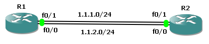
| | TASKS: - Configure IP addresses on R1 and R2 as per topology
- Configure Loopback interface on R2 10.1.1.1/32
- Configure 1.1.1.0 as primary static route
- Configure 1.1.2.0 as floating static route
- Verify results by shutting down primary route interface of R1, R2 and both.
|
| ! Configuration of R1
hostname R1
interface FastEthernet0/0
ip address 1.1.2.1 255.255.255.0
no shut
interface FastEthernet0/1
ip address 1.1.1.1 255.255.255.0
no shut
ip route 10.1.1.1 255.255.255.255 1.1.1.100
ip route 10.1.1.1 255.255.255.255 1.1.2.50 15
! Configuration of R2
hostname R2
interface Loopback0
ip address 10.1.1.1 255.255.255.255
interface FastEthernet0/0
ip address 1.1.2.50 255.255.255.0
no shut
interface FastEthernet0/1
ip address 1.1.1.100 255.255.255.0
no shut
| Explanation
Primary Static route with default Administrative distance
Floating Static route with administrative distance of 15
|
Verification
R1#show ip route
1.0.0.0/24 is subnetted, 2 subnets
C 1.1.1.0 is directly connected, FastEthernet0/1
C 1.1.2.0 is directly connected, FastEthernet0/0
10.0.0.0/32 is subnetted, 1 subnets
S 10.1.1.1 [1/0] via 1.1.1.100
Shut down R1 primary route interface and check routing table now
R1#show ip interface brief
Interface IP-Address OK? Method Status Protocol
FastEthernet0/0 1.1.2.1 YES manual up up
FastEthernet0/1 1.1.1.1 YES manual administratively down down
R1#sh ip route
1.0.0.0/24 is subnetted, 1 subnets
C 1.1.2.0 is directly connected, FastEthernet0/0
10.0.0.0/32 is subnetted, 1 subnets
S 10.1.1.1 [15/0] via 1.1.2.50

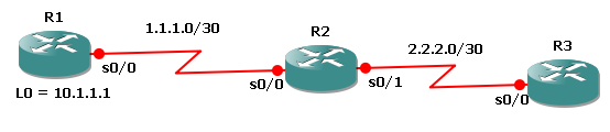
TASKS:
1. Configure IP Addresses as per diagram
2. Configure 5 subnet of 20.0.0.0/8 as loopback addresses in R3
3. Look into routing table inter-area routes
4. Configure Area Range command on R2 and see change in Routing table of R1. Area range command summarizes range and only work on Border Routers.
5. See Results by using Show ip route; show ip protocols
6. Dubug ip ospf adj and Debug ip ospf events
| ! R1 Configuration
hostname R1 !
interface Serial0/0
ip address 1.1.1.1 255.255.255.252
no shut
!
interface Serial0/1
ip address 2.2.2.1 255.255.255.252
no shut
!
router ospf 1
network 1.1.1.0 0.0.0.3 area 0
network 2.2.2.0 0.0.0.3 area 10
! R2 Configuration
hostname R2
interface Serial0/0
ip address 1.1.1.2 255.255.255.252
no shut
!
interface Serial0/1
ip address 3.3.3.1 255.255.255.252
no shut
!
router ospf 1
area 20 range 20.1.1.0 255.255.255.0
network 1.1.1.0 0.0.0.3 area 0
network 3.3.3.0 0.0.0.3 area 20
| ! R3 Configuration
hostname R3
interface Loopback0
ip address 20.1.1.1 255.255.255.255
interface Loopback1
ip address 20.1.1.2 255.255.255.255
interface Loopback2
ip address 20.1.1.3 255.255.255.255
interface Loopback3
ip address 20.1.1.4 255.255.255.255
interface Loopback4
ip address 20.1.1.5 255.255.255.255
!
interface Serial0/0
ip address 3.3.3.2 255.255.255.252
no shut
!
router ospf 1
network 3.3.3.0 0.0.0.3 area 20
network 20.1.1.1 0.0.0.0 area 20
network 20.1.1.2 0.0.0.0 area 20
network 20.1.1.3 0.0.0.0 area 20
network 20.1.1.4 0.0.0.0 area 20
network 20.1.1.5 0.0.0.0 area 20
! R4 Configuration
hostname R4
interface Serial0/0
ip address 2.2.2.2 255.255.255.252
no shut
!
router ospf 1
network 2.2.2.0 0.0.0.3 area 10
|
passive-interface command is used to block RIP broadcasts on an interface connected to a subnet of a RIP-enabled network. In simple words, Passive-interface command is used in all routing protocols to disable sending updates out from a specific interface. A RIP Passive Interface in a nut shell prevents the RIP routing process from sending multicast/broadcast updates out a specified interface. A RIP Passive interface however does not block unicast updates. Keep in mind a Passive Interface DOES NOT block multicast/broadcast updates therefore the router would still process received RIP updates
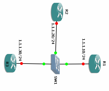
| | Tasks:
Configure IP addresses as per diagram
Configure Rip on all networks
Configure R3 Fast Ethernet 0/0 interface to start Rip unicast
Debug by using following commands.
show ip route
show ip route rip
sh ip protocol
debug ip rip events
debug ip rip database
|
| ! R1 Configuration
interface Loopback0
ip address 20.1.2.1 255.255.255.255
interface FastEthernet0/0
ip address 1.1.1.10 255.255.255.0
no shut
router rip
version 2
network 1.0.0.0
network 20.0.0.0
no auto-summary
! R2 Configuration
interface Loopback0
ip address 20.1.1.1 255.255.255.255
interface FastEthernet0/0
ip address 1.1.1.20 255.255.255.0
no shut
router rip
version 2
network 1.0.0.0
network 20.0.0.0
no auto-summary
! R3 Configuration
interface Loopback0
ip address 30.1.1.1 255.255.255.255
interface Loopback1
ip address 30.1.2.1 255.255.255.255
interface FastEthernet0/0
ip address 1.1.1.30 255.255.255.0
no shut
router rip
version 2
passive-interface FastEthernet0/0
network 1.0.0.0
network 30.0.0.0
neighbor 1.1.1.20
no auto-summary
| Explanation
Configuring Passive interface on F0/0 of Router 3
|

 RSS Feed