| | Task 1: Use simple authentication between R1 and R2. Key is simplekey
Task 2: Use md5 authentication between R3 and R2. Key is md5key
Debug to verify results
| | hostname R1
key chain simple
key 1
key-string simplekey
interface Loopback0
ip address 10.1.1.1 255.255.255.255
interface Loopback1
ip address 10.1.1.2 255.255.255.255
interface Serial0/0
no shut
ip address 1.1.1.1 255.255.255.252
ip rip authentication key-chain simple
clock rate 64000
router rip
version 2
network 1.0.0.0
network 10.0.0.0
hostname R2
key chain simple
key 1
key-string simplekey
key chain md5
key 1
key-string md5key
interface Serial0/0
no shut
ip address 1.1.1.2 255.255.255.252
ip rip authentication key-chain simple
interface Serial0/1
no shut
ip address 2.2.2.1 255.255.255.252
ip rip authentication mode md5
ip rip authentication key-chain md5
router rip
version 2
network 1.0.0.0
network 2.0.0.0
hostname R3
key chain md5
key 1
key-string md5key
interface Serial0/0
no shut
ip address 2.2.2.2 255.255.255.252
ip rip authentication mode md5
ip rip authentication key-chain md5
clock rate 64000
router rip
version 2
network 2.0.0.0
| Explanation
Key chain name defined
Key chain's key defined
Key's password or string defined forsimple authentication between R1 and R2
Authentication defined on serial interface. Authenticated keychain is "simple"
Keychain defined for simple authentication
Key chain defined for encrypted authentication i.e. MD5
Key chain named "simple" applied between R1 and R2
Encrypted Authentication applied on interface between R2 and R3
Authentication key chain applied
Encrypted key chain defined named md5.
Encrypted Authentication applied on interface between R2 and R3
Authentication key chain applied
|
 TASKs: - Confiigure IP addresses as per diagram
- Configure static ip address on R1 to reach network 2.2.2.0 and Default IP address on R3 to reach network 1.1.1.0
| ! R1 Configuration
hostname R1
interface FastEthernet0/0
ip address 1.1.1.1 255.255.255.252
no shut
ip route 2.2.2.0 255.255.255.252 1.1.1.2
! R2 Configuration
hostname R2
interface FastEthernet0/0
ip address 1.1.1.2 255.255.255.252
no shut
interface FastEthernet0/1
ip address 2.2.2.1 255.255.255.252
no shut
! R3 Configuration
hostname R3
interface FastEthernet0/0
ip address 2.2.2.2 255.255.255.252
no shut
ip route 0.0.0.0 0.0.0.0 2.2.2.1
|
Changing hostname to R1
Assigning ip address to an interface
Configuring static ip address on R1 to reach 2.2.2.0 network via next-hop 1.1.1.2
Configuring Default ip address on R3 to reach 1.1.1.0 network via 2.2.2.1 Hop
| Verification of routes
R1#show ip route
1.0.0.0/30 is subnetted, 1 subnets
C 1.1.1.0 is directly connected, FastEthernet0/0
2.0.0.0/30 is subnetted, 1 subnets
S 2.2.2.0 [1/0] via 1.1.1.2
R2#show ip route
1.0.0.0/30 is subnetted, 1 subnets
C 1.1.1.0 is directly connected, FastEthernet0/0
2.0.0.0/30 is subnetted, 1 subnets
C 2.2.2.0 is directly connected, FastEthernet0/1
R3#show ip route
Gateway of last resort is 2.2.2.1 to network 0.0.0.0
2.0.0.0/30 is subnetted, 1 subnets
C 2.2.2.0 is directly connected, FastEthernet0/0
S* 0.0.0.0/0 [1/0] via 2.2.2.1
Verification via Ping
R1#ping 2.2.2.1
Type escape sequence to abort.
Sending 5, 100-byte ICMP Echos to 2.2.2.1, timeout is 2 seconds:
!!!!!
Success rate is 100 percent (5/5), round-trip min/avg/max = 8/90/152 ms
R1#ping 2.2.2.2
Type escape sequence to abort.
Sending 5, 100-byte ICMP Echos to 2.2.2.2, timeout is 2 seconds:
!!!!!
Success rate is 100 percent (5/5), round-trip min/avg/max = 32/96/232 ms
IP SLA (Internet protocol service level agreement) is a feature of the Cisco Internetwork Operating System (Cisco IOS) that allows an IT professional to collect information about network performance in real time. Cisco IOS IP SLAs continuously collect data about such things as response times, latency, jitter and packet loss. This not only provides the network administrator with baseline information about network performance. IP SLAs are especially useful for wide area networks (WANs) that connect multiple geographies and needs to be monitored from one central location.
 Requirement:- Configure IP addresses as per topology
- Configure EIGRP among ISP1 routers and between ISP1 and ISP2
- Configure Default and static routes as per need between customers and ISPs
- Configure SLA for icmp echo between customer 3 and customer 1.
- Configure SLA for path-echo between customer1 and customer2
verify results by using following commands - debug ip sla trace
- show ip sla statistics
- debug ip sla err
| ! Customer1 Configuration
interface Loopback0
ip address 150.1.1.1 255.255.255.255
interface Serial0/0
ip address 10.1.1.129 255.255.255.252
no shut
ip route 0.0.0.0 0.0.0.0 10.1.1.130
ip sla responder
ip sla 10
path-echo 10.1.1.194
verify-data
frequency 10
ip sla schedule 10 life 40 start-time now
! Cutomer2 Configuration
interface Loopback0
ip address 15.1.1.1 255.255.255.255
interface Serial0/0
ip address 10.1.1.194 255.255.255.252
no shut
ip route 0.0.0.0 0.0.0.0 10.1.1.193
ip sla responder
! Customer3 Configuration
interface Loopback0
ip address 90.1.1.1 255.255.255.255
interface Serial0/0
ip address 11.1.1.194 255.255.255.252
no shut
ip route 0.0.0.0 0.0.0.0 11.1.1.193
ip sla 1
icmp-echo 150.1.1.1
verify-data
frequency 5
ip sla schedule 1 life 60 start-time now
! ISPR1 Configuration
interface FastEthernet0/0
ip address 10.1.1.1 255.255.255.252
no shut
interface Serial0/0
ip address 10.1.1.130 255.255.255.252
no shut
router eigrp 10
redistribute static
network 10.0.0.0
no auto-summary
ip route 150.1.1.1 255.255.255.255 10.1.1.129
! ISP2R2 Configuration
interface FastEthernet0/0
ip address 10.1.1.2 255.255.255.252
no shut
interface Serial0/0
ip address 10.1.1.193 255.255.255.252
no shut
interface Serial0/1
ip address 11.1.1.1 255.255.255.252
no shut
router eigrp 10
redistribute static
network 10.0.0.0
network 11.0.0.0
no auto-summary
ip route 15.1.1.1 255.255.255.255 10.1.1.194
! ISP2R1 Configuration
interface Serial0/0
ip address 11.1.1.2 255.255.255.252
no shut
interface Serial0/1
ip address 11.1.1.193 255.255.255.252
no shut
router eigrp 10
redistribute static
network 11.0.0.0
no auto-summary
ip route 90.1.1.1 255.255.255.255 11.1.1.194
| Configuration Explanation
Providing ip address to loopback 0
Providing IP address to serial 0/0
Default Route
The Cisco IOS IP SLAs Responder is a component embedded in the destination Cisco routing device
that allows the system to anticipate and respond to Cisco IOS IP SLAs request packets. The Cisco IOS
IP SLAs Responder provides an enormous advantage with accurate measurements without the need for dedicated probes
Enabling IP SLA. Number is the identification of this SLA and it is locally important.
The IP SLAs ICMP Path Echo operation records statistics for each hop along the path that the IP SLAs operation takes to reach its destination.
(Optional) Causes an IP SLAs operation to check each reply packet for data corruption.
(Optional) Set the rate at which a specified IP SLAs operation repeats.
Configures the scheduling parameters for a single IP SLAs operation. use the ip sla schedule command in global configuration mode
| Verification by Debugging
Customer3(config)#
*Mar 1 02:17:29.311: IP SLAs(1) Scheduler: Starting an operation
*Mar 1 02:17:29.311: IP SLAs(1) echo operation: Sending an echo operation -
destAddr=150.1.1.1, sAddr=11.1.1.194
*Mar 1 02:17:29.311: IP SLAs(1) echo operation: Sending ID: 7
*Mar 1 02:17:29.527: IP SLAs(1) echo operation: RTT=212
*Mar 1 02:17:29.527: IP SLAs(1) Scheduler: Updating result
*Mar 1 02:17:29.531: IP SLAs(1) Scheduler: life left 59784
*Mar 1 02:17:29.531: IP SLAs(1) Scheduler: is it random? 0
*Mar 1 02:17:29.531: IP SLAs(1) Scheduler: start wakeup timer, delay = 4780
*Mar 1 02:17:34.311: IP SLAs(1) Scheduler: saaSchedulerEventWakeup
*Mar 1 02:17:34.311: IP SLAs(1) Scheduler: Starting an operation
*Mar 1 02:17:34.311: IP SLAs(1) echo operation: Sending an echo operation -
destAddr=150.1.1.1, sAddr=11.1.1.194
*Mar 1 02:17:34.315: IP SLAs(1) echo operation: Sending ID: 7
*Mar 1 02:17:34.427: IP SLAs(1) echo operation: RTT=112
*Mar 1 02:17:34.427: IP SLAs(1) Scheduler: Updating result
*Mar 1 02:17:34.427: IP SLAs(1) Scheduler: life left 54884
*Mar 1 02:17:34.431: IP SLAs(1) Scheduler: is it random? 0
*Mar 1 02:17:34.431: IP SLAs(1) Scheduler: start wakeup timer, delay = 4880
Customer1(config)#
*Mar 1 02:33:24.391: IP SLAs(10) Scheduler: Starting an operation
*Mar 1 02:33:24.395: IP SLAs(10) pathEcho operation: Sending a pathEcho operation
*Mar 1 02:33:24.399: IP SLAs(10) pathEcho operation: Sending Packet to 10.1.1.194 with ttl = 1
*Mar 1 02:33:24.407: IP SLAs(10) pathEcho operation: Return Value of ! for target 10.1.1.130
*Mar 1 02:33:24.407: IP SLAs(10) pathEcho operation: Adding hop - 10.1.1.130
*Mar 1 02:33:24.407: IP SLAs(10) pathEcho operation: Sending Packet to 10.1.1.194 with ttl = 2
*Mar 1 02:33:24.619: IP SLAs(10) pathEcho operation: Return Value of ! for target 10.1.1.2
*Mar 1 02:33:24.623: IP SLAs(10) pathEcho operation: Adding hop - 10.1.1.2
*Mar 1 02:33:24.623: IP SLAs(10) pathEcho operation: Sending Packet to 10.1.1.194 with ttl = 3
*Mar 1 02:33:24.823: IP SLAs(10) pathEcho operation: Return Value of U for target 10.1.1.194
*Mar 1 02:33:24.823: IP SLAs(10) pathEcho operation: Adding hop - 10.1.1.194
*Mar 1 02:33:24.951: IP SLAs(10) pathEcho operation: Hop 10.1.1.130 Response Time 124
*Mar 1 02:33:25.103: IP SLAs(10) pathEcho operation: Hop 10.1.1.2 Response Time 152
*Mar 1 02:33:25.255: IP SLAs(10) pathEcho operation: Hop 10.1.1.194 Response Time 149
*Mar 1 02:33:25.255: IP SLAs(10) Scheduler: Updating result
*Mar 1 02:33:25.263: IP SLAs(10) Scheduler: life left 39128
*Mar 1 02:33:25.263: IP SLAs(10) Scheduler: is it random? 0
*Mar 1 02:33:25.263: IP SLAs(10) Scheduler: start wakeup timer, delay = 9128
Customer1(config)#
 Requirement: - Configure ip addresses as per topology
- Configure one loopback address on each router i.e. 10.10.10.10 on R1 ; 20.20.20.20 on R2 ; 30.30.30.30 on R3 ; 40.40.40.40 on R4 and 50.50.50.50 on R5
- Configure ospf on specified networks
- Configure ibgp and ebgp as per topology
- Configure MPLS on core network
- Verify connectivity annd communication via mpls
Verification commands: - traceroute ip 50.50.50.50 source 40.40.40.40
- traceroute mpls ipv4 50.50.50.50/32 (very imp)
- ping mpls ipv4 30.30.30.30/32
- sh ip route :: Show ip bgp :: clear ip bgp *
- show mpls ldp neigehbor
- show mpls forwarding
- show mpls ldp binding
| ! R1 configuration
hostname R1
ip cef
mpls label protocol ldp
interface Loopback0
ip address 10.10.10.10 255.255.255.0
interface Serial0/0
ip address 1.1.1.1 255.255.255.0
mpls ip
no shut
interface Serial0/1
ip address 9.9.9.1 255.255.255.252
no shut
router ospf 10
redistribute bgp 10 subnets
network 1.1.1.0 0.0.0.255 area 0
network 10.10.10.10 0.0.0.0 area 0
router bgp 10
neighbor 9.9.9.2 remote-as 100
neighbor 9.9.9.2 distribute-list 1 out
neighbor 30.30.30.30 remote-as 10
neighbor 30.30.30.30 update-source Loopback0
neighbor 30.30.30.30 next-hop-self
no auto-summary
access-list 1 deny 50.50.50.50
access-list 1 permit any
! R2 Configuration
hostname R2
ip cef
mpls label protocol ldp
interface Loopback0
ip address 20.20.20.20 255.255.255.255
interface Serial0/0
ip address 1.1.1.2 255.255.255.0
mpls ip
no shut
interface Serial0/1
ip address 1.1.10.1 255.255.255.0
mpls ip
no shut
router ospf 10
network 1.1.1.0 0.0.0.255 area 0
network 1.1.10.0 0.0.0.255 area 0
network 20.20.20.20 0.0.0.0 area 0
| ! R3 Configuration
hostname R3
ip cef
mpls label protocol ldp
interface Loopback0
ip address 30.30.30.30 255.255.255.255
interface Serial0/0
ip address 1.1.10.11 255.255.255.0
mpls ip
no shut
interface Serial0/1
ip address 6.6.6.1 255.255.255.252
no shut
router ospf 10
redistribute bgp 10 subnets
network 1.1.10.0 0.0.0.255 area 0
network 30.30.30.30 0.0.0.0 area 0
router bgp 10
neighbor 6.6.6.2 remote-as 200
neighbor 6.6.6.2 distribute-list 1 out
neighbor 10.10.10.10 remote-as 10
neighbor 10.10.10.10 update-source Loopback0
neighbor 10.10.10.10 next-hop-self
no auto-summary
access-list 1 deny 40.40.40.40
access-list 1 permit any
! R4 Configuration
hostname R4
interface Loopback0
ip address 40.40.40.40 255.255.255.255
interface Serial0/0
ip address 9.9.9.2 255.255.255.252
no shut
router bgp 100
network 40.40.40.40 mask 255.255.255.255
neighbor 9.9.9.1 remote-as 10
no auto-summary
ip route 0.0.0.0 0.0.0.0 9.9.9.1
! R5 Configuration
hostname R5
interface Loopback0
ip address 50.50.50.50 255.255.255.255
interface Serial0/0
ip address 6.6.6.2 255.255.255.252
no shut
router bgp 200
network 50.50.50.50 mask 255.255.255.255
neighbor 6.6.6.1 remote-as 10
no auto-summary
ip route 0.0.0.0 0.0.0.0 6.6.6.1
| Verification:
R4#traceroute ip 50.50.50.50 source 40.40.40.40
Type escape sequence to abort.
Tracing the route to 50.50.50.50
1 9.9.9.1 56 msec 4 msec 8 msec
2 1.1.1.2 [MPLS: Label 16 Exp 0] 72 msec 16 msec 0 msec
3 1.1.10.11 60 msec 44 msec 20 msec
4 6.6.6.2 64 msec * 132 msec
R1#show mpls forwarding
Local Outgoing Prefix Bytes tag Outgoing Next Hop
tag tag or VC or Tunnel Id switched interface
16 Pop tag 1.1.10.0/24 0 Se0/0 point2point
17 16 50.50.50.50/32 0 Se0/0 point2point
18 Pop tag 20.20.20.20/32 0 Se0/0 point2point
19 19 30.30.30.30/32 0 Se0/0 point2point
R1#
R2#show mpls ldp neighbor
Peer LDP Ident: 10.10.10.10:0; Local LDP Ident 20.20.20.20:0
TCP connection: 10.10.10.10.646 - 20.20.20.20.53911
State: Oper; Msgs sent/rcvd: 151/151; Downstream
Up time: 02:00:22
LDP discovery sources:
Serial0/0, Src IP addr: 1.1.1.1
Addresses bound to peer LDP Ident:
1.1.1.1 9.9.9.1 10.10.10.10
Peer LDP Ident: 30.30.30.30:0; Local LDP Ident 20.20.20.20:0
TCP connection: 30.30.30.30.37364 - 20.20.20.20.646
State: Oper; Msgs sent/rcvd: 145/147; Downstream
Up time: 01:59:44
LDP discovery sources:
Serial0/1, Src IP addr: 1.1.10.11
Addresses bound to peer LDP Ident:
1.1.10.11 6.6.6.1 30.30.30.30
In this scenerio; we are trying to communicate two customers via MPLS SP cloud.
A CE router ( customer edge router ) is a router located on the customer premises that provides an Ethernet interface between the customer's LAN and the provider's core network. CE routers, P (provider) routers and PE (provider edge) routers are components in an MPLS (multiprotocol label switching) architecture. Provider routers are located in the core of the provider or carrier's network. Provider edge routers sit at the edge of the network. CE routers connect to PE routers and PE routers connect to other PE routers over P routers.
 Requirement: - Configure IP address as per toplogy
- Configure 2.2.2.2 as PE2 router ID, 3.3.3.3 P2 router ID, 4.4.4.4 P1 router ID and 1.1.1.1 as PE1 router ID.
- Configure EIGRP as a routing protocol
- Configure MPLS with-in cloud.
- Verify communication via MPLS
Verificaton Command- show mpls ip binding
- show ip cef
- show mpls interfaces
- show mpls ldp discovery
- show mpls ldp nei
- show mpls forwarding-table
| ! CE1 Configuration
ip cef
interface FastEthernet1/0
ip address 200.1.2.1 255.255.255.0
no shut
router eigrp 10
network 200.1.2.0
no auto-summary
! CE2 Configuration
ip cef
interface Loopback0
ip address 10.1.1.1 255.255.255.0
interface FastEthernet1/0
ip address 200.1.1.1 255.255.255.0
no shut
router eigrp 10
network 10.0.0.0
network 200.1.1.0
no auto-summary
! PE1 Configuration
ip cef
mpls label protocol ldp
interface Loopback0
ip address 1.1.1.1 255.255.255.255
interface FastEthernet1/0
ip address 200.1.2.2 255.255.255.0
no shut
interface Serial2/0
ip address 200.1.7.1 255.255.255.0
mpls label protocol ldp
mpls ip
no shut
interface Serial2/1
ip address 200.1.6.1 255.255.255.0
mpls label protocol ldp
mpls ip
no shut
router eigrp 10
network 1.0.0.0
network 200.1.2.0
network 200.1.6.0
network 200.1.7.0
no auto-summary
! PE2 Configuration
ip cef
mpls label protocol ldp
interface Loopback0
ip address 2.2.2.2 255.255.255.255
interface FastEthernet1/0
ip address 200.1.1.2 255.255.255.0
no shut
interface Serial2/0
ip address 200.1.4.1 255.255.255.0
mpls label protocol ldp
mpls ip
no shut
!
interface Serial2/1
ip address 200.1.3.1 255.255.255.0
mpls label protocol ldp
mpls ip
no shut
router eigrp 10
network 2.0.0.0
network 200.1.1.0
network 200.1.3.0
network 200.1.4.0
no auto-summary
! P1 Configuration
ip cef
mpls label protocol ldp
interface Loopback0
ip address 4.4.4.4 255.255.255.255
interface Serial1/0
ip address 200.1.7.2 255.255.255.0
mpls label protocol ldp
mpls ip
no shut
!
interface Serial1/1
ip address 200.1.4.2 255.255.255.0
mpls label protocol ldp
mpls ip
no shut
!
interface Serial1/2
ip address 200.1.5.2 255.255.255.0
mpls label protocol ldp
mpls ip
no shut
router eigrp 10
network 4.0.0.0
network 200.1.4.0
network 200.1.5.0
network 200.1.7.0
no auto-summary
!P2 Configuration
ip cef
mpls label protocol ldp
interface Loopback0
ip address 3.3.3.3 255.255.255.255
!
interface Serial1/0
ip address 200.1.6.2 255.255.255.0
mpls label protocol ldp
mpls ip
no shut
!
interface Serial1/1
ip address 200.1.3.2 255.255.255.0
mpls label protocol ldp
mpls ip
no shut
!
interface Serial1/2
ip address 200.1.5.1 255.255.255.0
mpls label protocol ldp
mpls ip
no shut
router eigrp 10
network 3.0.0.0
network 200.1.3.0
network 200.1.5.0
network 200.1.6.0
no auto-summary
| Configuration Explanation
Cisco's Express Forwarding (CEF) is an Layer 3 fastest switching technology by which Cisco router forwards packets from ingress to egress interfaces.
Note: This is a essential command
For explanation; See above
Enabling IP address to loopback interface
Enabling EIGRP autonomous no 10
See above for command explanation
Enable LDP protocol globally. MPLS Label Distribution Protocol (LDP) enables peer label switch routers (LSRs) in an MPLS network to exchange label binding information for supporting hop-by-hop forwarding in an MPLS network
Globally enabling MPLS forwarding does not enable it on the router interfaces. You must enable MPLS forwarding on the interfaces as well as for the router. | CE1#traceroute 10.1.1.1 ====> Look at the output; MPLs is working
Type escape sequence to abort.
Tracing the route to 10.1.1.1
1 200.1.2.2 80 msec 44 msec 32 msec
2 200.1.7.2 [MPLS: Label 23 Exp 0] 80 msec 64 msec 60 msec
3 200.1.4.1 [MPLS: Label 23 Exp 0] 172 msec 60 msec 76 msec
4 200.1.1.1 92 msec * 176 msec
check all verification commands by yourself.
In this scenario; We are trying to built a topology in which four customers wanna communicate each other via frame relay cloud. Normally labs are done with one FR device but what about when we are working as a WAN service provider having so many devices in their cloud. Let's see how customers of TelcoRemote2 will communicate to customer of TelcoKHI.
We will built a tunnel for this purpose and use OSPF as a routing protocol between Cloud. Let's see detail
 Requirement:- Configure all IP addresses as per topology
- Assign DLCI's to all customers
- Assign Route to all customers so that they will communicate each other seamlessly
- Configure OSPF area 0 for network 10.1.1.0 and 20.1.1.0
- Configure tunnel so that Remote customer can communicate to Site1, 2 and 3 customers.
- Verify connectivity with
ping command
show frame-relay map
show frame-relay route
show frame-relay pvc
debug frame-relay packet
debug frame-relay pvc
debug frame-relay event
| !CustomerSite1 Configuration
interface Serial0/0
ip address 1.1.1.1 255.255.255.0
encapsulation frame-relay
frame-relay interface-dlci 101
frame-relay interface-dlci 102
frame-relay interface-dlci 103
frame-relay interface-dlci 104
no shut
!CustomerSite2 Configuration
interface Serial0/0
ip address 2.2.2.2 255.255.255.0
encapsulation frame-relay
frame-relay interface-dlci 201
frame-relay interface-dlci 202
frame-relay interface-dlci 203
frame-relay interface-dlci 204
no shut
! CustomerSite3 Configuration
interface Serial0/0
ip address 3.3.3.3 255.255.255.0
encapsulation frame-relay
frame-relay interface-dlci 301
frame-relay interface-dlci 302
frame-relay interface-dlci 303
frame-relay interface-dlci 304
no shut
! Telco remote2 Configuration
frame-relay switching
interface Serial0/0
no ip address
encapsulation frame-relay
clock rate 64000
frame-relay intf-type dce
frame-relay route 102 interface Serial0/1 201
frame-relay route 103 interface Serial0/2 301
frame-relay route 104 interface Tunnel0 401
no shut
interface Serial0/1
no ip address
encapsulation frame-relay
clock rate 64000
frame-relay intf-type dce
frame-relay route 201 interface Serial0/0 102
frame-relay route 203 interface Serial0/2 302
frame-relay route 204 interface Tunnel0 402
no shut
interface Serial0/2
no ip address
encapsulation frame-relay
clock rate 64000
frame-relay intf-type dce
frame-relay route 301 interface Serial0/0 103
frame-relay route 302 interface Serial0/1 203
frame-relay route 304 interface Tunnel0 403
no shut
interface fastethernet 0/0
ip address 10.1.1.1 255.255.255.252
no shut
interface tunnel 0
no ip address
tunnel source 10.1.1.1
tunnel destination 20.1.1.1
Router OSPF 10
network 10.1.1.0 0.0.0.3 area 0
! R7 Configuration
interface fastethernet 0/0
ip address 10.1.1.2 255.255.255.252
no shut
interface fastethernet 0/1
ip address 20.1.1.2 255.255.255.252
no shut
Router OSPF 10
network 10.1.1.0 0.0.0.3 area 0
network 20.1.1.0 0.0.0.3 area 0
! Telco KHI Configuration
frame-relay switching
interface Serial0/2
no ip address
encapsulation frame-relay
clock rate 64000
frame-relay intf-type dce
! Note both dlcis are same in all routes
frame-relay route 401 interface Tunnel0 401
frame-relay route 402 interface Tunnel0 402
frame-relay route 403 interface Tunnel0 403
no shut
interface fastethernet 0/0
ip address 20.1.1.1 255.255.255.252
no shut
interface tunnel 0
no ip address
tunnel source 20.1.1.1
tunnel destination 10.1.1.1
Router OSPF 10
network 20.1.1.0 0.0.0.3 area 0
! RemoteCustomer Configuration
interface Serial0/0
ip address 15.15.15.1 255.255.255.0
encapsulation frame-relay
frame-relay interface-dlci 401
frame-relay interface-dlci 402
frame-relay interface-dlci 403
frame-relay interface-dlci 404
no shut
| Configuration Explanation
Configuring IP on customer interface
encapsulation frame-relay command sets the frame encapsulation type. There are two types of Frame Relay encapsulations: Cisco and IETF. Cisco is the default.
We are putting many DLCI's to one physical serial interface.
See Site1 Explanation
See Site1 Explanation
This is a key command on FR switches on service provider side. Forget this command; Forget FR switching. Anyhow; If you try to configure interface type dce without this; you will get error.
As this interface word as a FR enabled interface; it donot require IP address.
Setting encapsulation type
Setting clock rate
FR switch interface must be DCE
This command is telling that DLCI 102, 103, 104 should route toward said interface
Creating tunnel from source 10.1.1.1 (interface F0/0) to destination 20.1.1.1 (int F0/0)
This is a key for tunneling Frame relay. Both DLCI's should be same in each command else you will find status Inactive
|
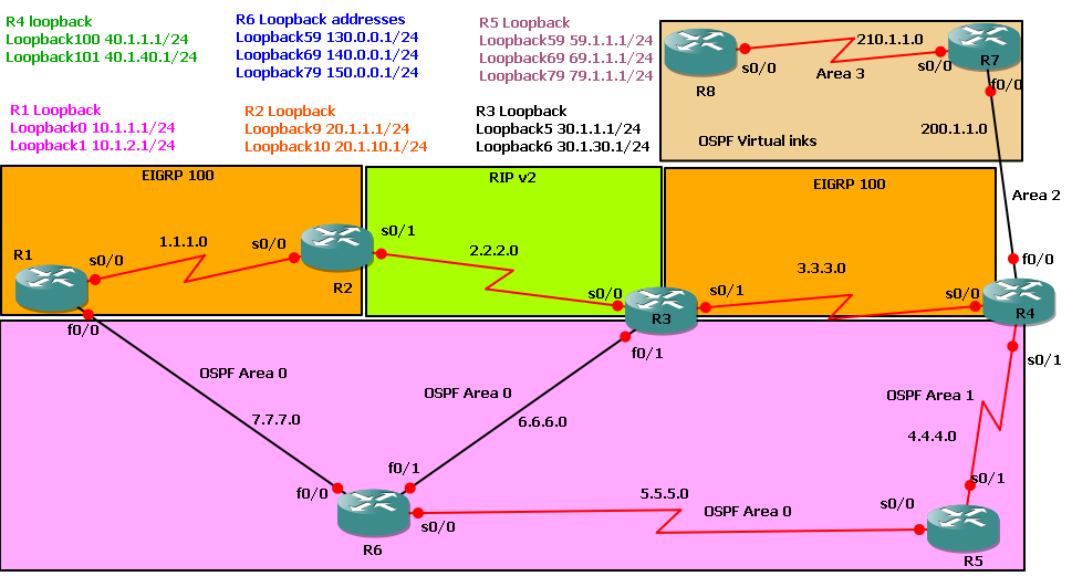
Requirement:- Configure IP addresses as per diagram
- Configure loopback addresses as per diagram
- All routers must reach every route in the network
- How many virtual links and tunnels we need to configure for this topology so that R8 will have all routes and why?
- 1 virtual link
- 2 virtual link
- 1 virtual link and 1 tunnel
- More then 2 virtual links
- Test connectivity by ping
- How many pings do we need to reach all networks from R8? Can pinging 255.255.255.255 will help us reach all networks in one go? If yes Why and If no then why not?
- Verify configuration by using following commands
- Show ip route
- show ip eigrp interfaces
- show ip eigrp neighbors
- show ip eigrp topology
- show ip eigrp traffic
- show ip protocol
- show ip ospf border-routers
- show ip ospf database
- show ip ospf interface
- show ip ospf neighbor
- show ip ospf virtual-links
- show ip rip database
| ! R1 configuration
interface Loopback0
ip address 10.1.1.1 255.255.255.0
no shut
interface Loopback1
ip address 10.1.2.1 255.255.255.0
no shut
interface FastEthernet0/0
ip address 7.7.7.2 255.255.255.252
no shut
interface Serial0/0
ip address 1.1.1.1 255.255.255.252
no shut
router eigrp 100
network 1.0.0.0
network 10.0.0.0
no auto-summary
router ospf 1
network 7.7.7.0 0.0.0.3 area 0
! R3 configuration
interface Loopback5
ip address 30.1.1.1 255.255.255.0
interface Loopback6
ip address 30.1.30.1 255.255.255.0
interface FastEthernet0/1
ip address 6.6.6.2 255.255.255.252
no shut
interface Serial0/1
ip address 3.3.3.1 255.255.255.252
no shut
router eigrp 100
redistribute rip metric 10 10 10 10 10
redistribute ospf 1 metric 10 10 10 10 10
network 3.0.0.0
no auto-summary
router ospf 1
redistribute eigrp 100 metric 10 subnets
redistribute rip metric 10 subnets
network 6.6.6.0 0.0.0.3 area 0
router rip
version 2
redistribute eigrp 100 metric 10
redistribute ospf 1 metric 10
network 2.0.0.0
network 30.0.0.0
no auto-summary
! R5 configuration
interface Loopback59
ip address 59.1.1.1 255.255.255.0
interface Loopback69
ip address 69.1.1.1 255.255.255.0
interface Loopback79
ip address 79.1.1.1 255.255.255.0
interface Serial0/0
ip address 5.5.5.2 255.255.255.252
no shut
interface Serial0/1
ip address 4.4.4.2 255.255.255.252
no shut
router ospf 1
area 1 virtual-link 40.1.40.1
network 4.4.4.0 0.0.0.3 area 1
network 5.5.5.0 0.0.0.3 area 0
network 59.1.1.0 0.0.0.255 area 0
network 69.1.1.0 0.0.0.255 area 0
network 79.1.1.0 0.0.0.255 area 1
! R7 configuration
interface FastEthernet0/0
ip address 200.1.1.2 255.255.255.252
no shut
interface Serial0/0
ip address 210.1.1.1 255.255.255.252
clock rate 64000
no shut
router ospf 1
log-adjacency-changes
area 2 virtual-link 40.1.40.1
network 200.1.1.0 0.0.0.3 area 2
network 210.1.1.0 0.0.0.3 area 3 | ! R2 configuration
interface Loopback9
ip address 20.1.1.1 255.255.255.0
interface Loopback10
ip address 20.1.10.1 255.255.255.0
interface Serial0/0
ip address 1.1.1.2 255.255.255.252
no shut
interface Serial0/1
ip address 2.2.2.1 255.255.255.252
no shut
router eigrp 100
redistribute rip metric 10 10 10 10 10
network 1.0.0.0
network 20.0.0.0
no auto-summary
router rip
version 2
redistribute eigrp 100 metric 10
network 2.0.0.0
no auto-summary
! R4 configuration
interface Loopback100
ip address 40.1.1.1 255.255.255.0
interface Loopback101
ip address 40.1.40.1 255.255.255.0
interface FastEthernet0/0
ip address 200.1.1.1 255.255.255.252
no shut
interface Serial0/0
ip address 3.3.3.2 255.255.255.252
no shut
interface Serial0/1
ip address 4.4.4.1 255.255.255.252
no shut
router eigrp 100
network 3.0.0.0
network 40.0.0.0
no auto-summary
router ospf 1
area 1 virtual-link 79.1.1.1
area 2 virtual-link 210.1.1.1
network 4.4.4.0 0.0.0.3 area 1
network 200.1.1.0 0.0.0.3 area 2
! R6 configuration
interface Loopback59
ip address 130.0.0.1 255.255.255.0
interface Loopback69
ip address 140.0.0.1 255.255.255.0
interface Loopback89
ip address 150.0.0.1 255.255.255.0
interface FastEthernet0/0
ip address 7.7.7.1 255.255.255.252
no shut
interface Serial0/0
ip address 5.5.5.1 255.255.255.252
clock rate 64000
no shut
interface FastEthernet0/1
ip address 6.6.6.1 255.255.255.252
no shut
router ospf 1
network 5.5.5.0 0.0.0.3 area 0
network 6.6.6.0 0.0.0.3 area 0
network 7.7.7.0 0.0.0.3 area 0
network 130.0.0.0 0.0.0.255 area 0
network 140.0.0.0 0.0.0.255 area 1
network 150.0.0.0 0.0.0.255 area 0
! R8 configuration
interface Serial0/0
ip address 210.1.1.2 255.255.255.252
no shut
router ospf 1
network 210.1.1.0 0.0.0.3 area 3
|
 OSPF stands for Open Shortest Path First. It is an internal routing protocol of the autonomous system based on link state. Routers running the SPF (Shortest Path First) algorithm Dijkshtra to be precise build a shortest path tree that takes itself as the root, and the tree gives out the route to nodes in the autonomous system. Within OSPF there can be Point-to-Point networks or Multi-Access networks. The Multi-Access networks could be one of the following: - Broadcast Network: A single message can be sent to all routers
- Non-Broadcast Multi-Access (NBMA) Network: Has no broadcast ability, ISDN, ATM, Frame Relay and X.25 are examples of NBMA networks.
- Point to Multipoint Network: Used in group mode Frame Relay networks.
Requirement:- Enable and configure interfaces as per topology diagram
- Configure one loop back addresses on each router
- Configure OSPF area 0 on both routers so that they both can get all routes
| ! R2 Configuration
interface Loopback0
ip address 10.1.1.1 255.255.255.0
interface Serial0/0
ip address 1.1.1.1 255.255.255.252
no shut
router ospf 10
network 1.1.1.0 0.0.0.3 area 0
network 10.1.1.0 0.0.0.255 area 0
| ! R3 Configuration
interface Loopback0
ip address 100.1.1.1 255.255.255.255
!
interface Serial0/0
ip address 1.1.1.2 255.255.255.252
no shut
!
router ospf 10
network 1.1.1.0 0.0.0.3 area 0
network 100.1.1.1 0.0.0.0 area 0
| Verification commands
R2#show ip ospf neighbor ==========> To find out information about OSPF neighbors
Neighbor ID Pri State Dead Time Address Interface
100.1.1.1 0 FULL/ - 00:00:36 1.1.1.2 Serial0/0
Look at the neighbor ID; its the loopback address
R3#show ip ospf neighbor
Neighbor ID Pri State Dead Time Address Interface
10.1.1.1 0 FULL/ - 00:00:30 1.1.1.1 Serial0/0
Look at the neighbor ID; its the loopback address
R2#show ip route ospf ==========> Only OSPF routes
100.0.0.0/32 is subnetted, 1 subnets
O 100.1.1.1 [110/65] via 1.1.1.2, 00:34:12, Serial0/0
R3#show ip route ospf
10.0.0.0/32 is subnetted, 1 subnets
O 10.1.1.1 [110/65] via 1.1.1.1, 00:34:12, Serial0/0
R2#show ip route ==========> ALL routes coming to routing table
Gateway of last resort is not set
1.0.0.0/30 is subnetted, 1 subnets
C 1.1.1.0 is directly connected, Serial0/0
100.0.0.0/32 is subnetted, 1 subnets
O 100.1.1.1 [110/65] via 1.1.1.2, 00:36:01, Serial0/0
10.0.0.0/24 is subnetted, 1 subnets
C 10.1.1.0 is directly connected, Loopback0
R3#show ip route
Gateway of last resort is not set
1.0.0.0/30 is subnetted, 1 subnets
C 1.1.1.0 is directly connected, Serial0/0
100.0.0.0/32 is subnetted, 1 subnets
C 100.1.1.1 is directly connected, Loopback0
10.0.0.0/32 is subnetted, 1 subnets
O 10.1.1.1 [110/65] via 1.1.1.1, 00:36:01, Serial0/0
R2#show ip protocols
Routing Protocol is "ospf 10" ==========> This is OSPF process ID
Outgoing update filter list for all interfaces is not set
Incoming update filter list for all interfaces is not set
Router ID 10.1.1.1 ==========> Router ID
Number of areas in this router is 1. 1 normal 0 stub 0 nssa
Maximum path: 4
Routing for Networks:
1.1.1.0 0.0.0.3 area 0
10.1.1.0 0.0.0.7 area 0
10.1.1.0 0.0.0.255 area 0
Reference bandwidth unit is 100 mbps
Routing Information Sources:
Gateway Distance Last Update
100.1.1.1 110 00:38:01 ==========> Administrative distance
Distance: (default is 110) ==========> OSPF default Administrative distance
R3#show ip protocols
Routing Protocol is "ospf 10"
Outgoing update filter list for all interfaces is not set
Incoming update filter list for all interfaces is not set
Router ID 100.1.1.1
Number of areas in this router is 1. 1 normal 0 stub 0 nssa
Maximum path: 4
Routing for Networks:
1.1.1.0 0.0.0.3 area 0
100.1.1.1 0.0.0.0 area 0
Reference bandwidth unit is 100 mbps
Routing Information Sources:
Gateway Distance Last Update
10.1.1.1 110 00:38:01
Distance: (default is 110)
ODR is not a routing protocol but an enhancement to CDP as it can propogate prefixes and only add 5 bytes into CDP. ODR must only be enabled on stub router. ODR will not work if other routing protocols are running. CDP should be running on all routers. We need to run ODR on hub router and all other spokes send their connected interfaces information to Hub via ODR (CDP update). Please note that we cannot redistribute static or dynamic routes to ODR but can redistribute ODR routes to dunamic protocols.
You can also load balance via ODR if you have multiple Hubs.
 Requirement:- In this topology R3 is a spoke and R2 is a Hub. We will running EIGRP between R1 and R2.
- R3 should send its loop-back (connected interfaces) information to the whole network without using static routing or dynamic routing protocols.
- R3 should learn EIGRP routes
| ! R1 Configuration
interface FastEthernet0/0
ip address 1.1.1.1 255.0.0.0
no shut
router eigrp 10
network 1.0.0.0
! R2 Configuration
router odr
interface FastEthernet0/0
ip address 1.1.1.2 255.0.0.0
no shutdown
interface Serial0/0
ip address 2.2.2.1 255.0.0.0
no shutdown
router eigrp 10
network 1.0.0.0
redistribute odr metric 10 10 10 10 10
! R3 Configuration
interface Loopback0
ip address 40.1.1.1 255.255.255.255
interface Loopback1
ip address 40.1.1.2 255.255.255.255
interface Serial0/0
ip address 2.2.2.2 255.0.0.0
no shutdown
| Configuration Explanation
This command is letting R2 to send itself as a default route to all spoke routers i.e. R1 and will get connected information update from neighbors CDP update
Redistributing ODR routes to EIGRP
Connected loopback interface
Connected loopback interface
| Verification
R3#show ip route odr
o* 0.0.0.0/0 [160/1] via 2.2.2.1, 00:00:45, Serial0/0
R3#show ip route
Gateway of last resort is 2.2.2.1 to network 0.0.0.0
C 2.0.0.0/8 is directly connected, Serial0/0
40.0.0.0/32 is subnetted, 2 subnets
C 40.1.1.1 is directly connected, Loopback0
C 40.1.1.2 is directly connected, Loopback1
o* 0.0.0.0/0 [160/1] via 2.2.2.1, 00:00:13, Serial0/0
This output shows that by configuring R2 as ODR; R1 (spoke) gets default route toward hub (R2)
R2#show ip route
C 1.0.0.0/8 is directly connected, FastEthernet0/0
C 2.0.0.0/8 is directly connected, Serial0/0
40.0.0.0/32 is subnetted, 2 subnets
o 40.1.1.1 [160/1] via 2.2.2.2, 00:00:30, Serial0/0
o 40.1.1.2 [160/1] via 2.2.2.2, 00:00:30, Serial0/0
R2 has learnt both ODR routes from CDP update
R1#show ip route
C 1.0.0.0/8 is directly connected, FastEthernet0/0
40.0.0.0/32 is subnetted, 2 subnets
D EX 40.1.1.1 [170/256028160] via 1.1.1.2, 00:00:37, FastEthernet0/0
D EX 40.1.1.2 [170/256028160] via 1.1.1.2, 00:00:37, FastEthernet0/0
Redistributed ODR routes to EIGRP
 Requirement:
Bat-man router F0/0 should get IP address from DHCP server configured on DHCP-Switch. Let's see how we can do it
| Device Configuration
! batman-router
interface FastEthernet0/0
ip address dhcp
speed 100
full-duplex
no shut
! DHCP-SWITCH Configuration
hostname DHCP-SWITCH
interface fastEthernet 1/0
no shut
speed 100
duplex full
switchport access vlan 5
int vlan 5
ip add 20.10.10.1 255.255.255.0
no shut
exit
ip routing
ip dhcp excluded-address 20.10.10.1 20.10.10.3
ip dhcp pool dhcp-pool
network 20.10.10.0 255.255.255.128
default-router 20.10.10.1
domain-name dhcp.com.pk
lease 1 12
| Explanation
Assign IP address via DHCP. When DHCP client will boot, the client will begin sending packets to its default router. The IP address of the default router should be on the same subnet as the client.
Changing Host name
This is a switch interface
Creating vlan. We will assign this vlan ip as adefault gateway address
Assigning ip to SVI interface
Address to exclude from ip pool. Actually we are already using or have to use these addresses in future and we donot want dhcp to assign these ip addresses to any other client
Assigning dhcp pool name
Assigning ip addresses to dhcp pool
This command will make 20.10.10.1 as a default gateway and propagate this information to all neighbors
Assigning domain name
IP lease time is 1 day and 12 hours
| Verification of DHCP IP assignment and detailed debugging
batman-router#sh ip route
Gateway of last resort is 20.10.10.1 to network 0.0.0.0
Have you noticed gateway of last resort. This is due to default-router command configured on dhcp-switch
20.0.0.0/25 is subnetted, 1 subnets
C 20.10.10.0 is directly connected, FastEthernet0/0
S* 0.0.0.0/0 [254/0] via 20.10.10.1
Have you noticed default route. This is due to default-router command configured on dhcp-switch
batman-router#show ip interface brief
Interface IP-Address OK? Method Status Protocol
FastEthernet0/0 20.10.10.5 YES DHCP up up
batman-router#debug dhcp detail
*Mar 1 00:17:37.179: DHCP: DHCP client process started: 10
*Mar 1 00:17:37.211: RAC: Starting DHCP discover on FastEthernet0/0
*Mar 1 00:17:37.211: DHCP: Try 1 to acquire address for FastEthernet0/0
*Mar 1 00:17:37.239: DHCP: allocate request
*Mar 1 00:17:37.243: DHCP: zapping entry in DHC_PURGING state for Fa0/0
*Mar 1 00:17:37.243: DHCP: deleting entry 673E86B4 20.10.10.4 from list
*Mar 1 00:17:37.247: Temp IP addr: 20.10.10.4 for peer on Interface: FastEthernet0/0
*Mar 1 00:17:37.251: Temp sub net mask: 255.255.255.128
*Mar 1 00:17:37.251: DHCP Lease server: 20.10.10.1, state: 11 Purging
*Mar 1 00:17:37.255: DHCP transaction id: 2B5
*Mar 1 00:17:37.255: Lease: 129600 secs, Renewal: 64800 secs, Rebind: 113400 secs
*Mar 1 00:17:37.259: Next timer fires after: 00:00:24
*Mar 1 00:17:37.263: Retry count: 0 Client-ID: cisco-c400.04b8.0000-Fa0/0
*Mar 1 00:17:37.263: Client-ID hex dump: 636973636F2D633430302E303462382E
*Mar 1 00:17:37.275: 303030302D4661302F30
*Mar 1 00:17:37.283: Hostname: Router
*Mar 1 00:17:37.287: DHCP: new entry. add to queue, interface FastEthernet0/0
*Mar 1 00:17:37.291: DHCP: SDiscover attempt # 1 for entry:
*Mar 1 00:17:37.291: Temp IP addr: 0.0.0.0 for peer on Interface: FastEthernet0/0
*Mar 1 00:17:37.295: Temp sub net mask: 0.0.0.0
*Mar 1 00:17:37.295: DHCP Lease server: 0.0.0.0, state: 3 Selecting
*Mar 1 00:17:37.299: DHCP transaction id: 20C2
*Mar 1 00:17:37.303: Lease: 0 secs, Renewal: 0 secs, Rebind: 0 secs
*Mar 1 00:17:37.303: Next timer fires after: 00:00:04
*Mar 1 00:17:37.307: Retry count: 1 Client-ID: cisco-c400.04b8.0000-Fa0/0
*Mar 1 00:17:37.307: Client-ID hex dump: 636973636F2D633430302E303462382E
*Mar 1 00:17:37.319: 303030302D4661302F30
*Mar 1 00:17:37.327: Hostname: batman-router
*Mar 1 00:17:37.331: DHCP: SDiscover: sending 302 byte length DHCP packet
*Mar 1 00:17:37.331: DHCP: SDiscover 302 bytes
*Mar 1 00:17:37.335: B'cast on FastEthernet0/0 interface from 0.0.0.0
*Mar 1 00:17:39.163: %LINK-3-UPDOWN: Interface FastEthernet0/0, changed state to up
*Mar 1 00:17:39.767: DHCP: Received a BOOTREP pkt
*Mar 1 00:17:39.771: DHCP: Scan: Message type: DHCP Offer
*Mar 1 00:17:39.775: DHCP: Scan: Server ID Option: 20.10.10.1 = 140A0A01
*Mar 1 00:17:39.775: DHCP: Scan: Lease Time: 129600
*Mar 1 00:17:39.779: DHCP: Scan: Renewal time: 64800
*Mar 1 00:17:39.779: DHCP: Scan: Rebind time: 113400
*Mar 1 00:17:39.783: DHCP: Scan: Subnet Address Option: 255.255.255.128
*Mar 1 00:17:39.783: DHCP: Scan: Router Option: 20.10.10.1
*Mar 1 00:17:39.787: DHCP: Scan: Domain Name: dhcp.com.pk
*Mar 1 00:17:39.787: DHCP: rcvd pkt source: 20.10.10.1, destination: 255.255.255.255
*Mar 1 00:17:39.791: UDP sport: 43, dport: 44, length: 308
*Mar 1 00:17:39.795: DHCP op: 2, htype: 1, hlen: 6, hops: 0
*Mar 1 00:17:39.795: DHCP server identifier: 20.10.10.1
*Mar 1 00:17:39.799: xid: 20C2, secs: 0, flags: 8000
*Mar 1 00:17:39.799: client: 0.0.0.0, your: 20.10.10.5
*Mar 1 00:17:39.803: srvr: 0.0.0.0, gw: 0.0.0.0
*Mar 1 00:17:39.803: options block length: 60
*Mar 1 00:17:39.807: DHCP Offer Message Offered Address: 20.10.10.5
*Mar 1 00:17:39.811: DHCP: Lease Seconds: 129600 Renewal secs: 64800 Rebind secs: 1 13400
*Mar 1 00:17:39.815: DHCP: Server ID Option: 20.10.10.1
*Mar 1 00:17:39.815: DHCP: offer received from 20.10.10.1
*Mar 1 00:17:39.819: DHCP: SRequest attempt # 1 for entry:
*Mar 1 00:17:39.819: Temp IP addr: 20.10.10.5 for peer on Interface: FastEthernet0/0
*Mar 1 00:17:39.823: Temp sub net mask: 255.255.255.128
*Mar 1 00:17:39.823: DHCP Lease server: 20.10.10.1, state: 4 Requesting
*Mar 1 00:17:39.823: DHCP transaction id: 20C2
*Mar 1 00:17:39.823: Lease: 129600 secs, Renewal: 0 secs, Rebind: 0 secs
*Mar 1 00:17:39.823: Next timer fires after: 00:00:03
*Mar 1 00:17:39.823: Retry count: 1 Client-ID: cisco-c400.04b8.0000-Fa0/0
*Mar 1 00:17:39.823: Client-ID hex dump: 636973636F2D633430302E303462382E
*Mar 1 00:17:39.823: 303030302D4661302F30
*Mar 1 00:17:39.823: Hostname: batman-router
*Mar 1 00:17:39.823: DHCP: SRequest- Server ID option: 20.10.10.1
*Mar 1 00:17:39.823: DHCP: SRequest- Requested IP addr option: 20.10.10.5
*Mar 1 00:17:39.823: DHCP: SRequest placed lease len option: 129600
*Mar 1 00:17:39.823: DHCP: SRequest: 320 bytes
*Mar 1 00:17:39.823: DHCP: SRequest: 320 bytes
*Mar 1 00:17:39.827: B'cast on FastEthernet0/0 interface from 0.0.0.0
*Mar 1 00:17:39.911: DHCP: Received a BOOTREP pkt
*Mar 1 00:17:39.911: DHCP: Scan: Message type: DHCP Ack
*Mar 1 00:17:39.915: DHCP: Scan: Server ID Option: 20.10.10.1 = 140A0A01
*Mar 1 00:17:39.915: DHCP: Scan: Lease Time: 129600
*Mar 1 00:17:39.919: DHCP: Scan: Renewal time: 64800
*Mar 1 00:17:39.919: DHCP: Scan: Rebind time: 113400
*Mar 1 00:17:39.923: DHCP: Scan: Subnet Address Option: 255.255.255.128
*Mar 1 00:17:39.923: DHCP: Scan: Router Option: 20.10.10.1
*Mar 1 00:17:39.927: DHCP: Scan: Domain Name: dhcp.com.pk
*Mar 1 00:17:39.931: DHCP: rcvd pkt source: 20.10.10.1, destination: 255.255.255.255
*Mar 1 00:17:39.931: UDP sport: 43, dport: 44, length: 308
*Mar 1 00:17:39.935: DHCP op: 2, htype: 1, hlen: 6, hops: 0
*Mar 1 00:17:39.935: DHCP server identifier: 20.10.10.1
*Mar 1 00:17:39.939: xid: 20C2, secs: 0, flags: 8000
*Mar 1 00:17:39.939: client: 0.0.0.0, your: 20.10.10.5
*Mar 1 00:17:39.943: srvr: 0.0.0.0, gw: 0.0.0.0
*Mar 1 00:17:39.947: options block length: 60
*Mar 1 00:17:39.947: DHCP Ack Message
*Mar 1 00:17:39.951: DHCP: Lease Seconds: 129600 Renewal secs: 64800 Rebind secs: 1 13400
*Mar 1 00:17:39.951: DHCP: Server ID Option: 20.10.10.1
*Mar 1 00:17:40.163: %LINEPROTO-5-UPDOWN: Line protocol on Interface FastEthernet0/0, change d state to up
*Mar 1 00:17:42.987: DHCP: Releasing ipl options:
*Mar 1 00:17:42.987: DHCP: Applying DHCP options:
*Mar 1 00:17:42.991: Setting default_gateway to 20.10.10.1
*Mar 1 00:17:42.991: Adding default route 20.10.10.1
*Mar 1 00:17:43.995: Setting default domain to dhcp.com.pk
*Mar 1 00:17:43.995: DHCP Client Pooling: ***Allocated IP address: 20.10.10.5
*Mar 1 00:17:44.071: Allocated IP address = 20.10.10.5 255.255.255.128
*Mar 1 00:17:44.075: %DHCP-6-ADDRESS_ASSIGN: Interface FastEthernet0/0 assigned DHCP address 20.10.10.5, mask 255.255.255.128, hostname batman-router
|

 RSS Feed